
1. 簡介
ARCore 這個平台可讓您在行動裝置上建構擴增實境 (AR) 應用程式,Google 的 ARCore Depth API 提供 ARCore 工作階段中每個影格的深度圖片存取權。每個深度影像中的像素都會提供相機與環境之間的距離。
Raw Depth API 可提供未透過螢幕空間篩選作業傳遞的深度圖片,這些作業是為了使結果產生平滑和插入而設計。這些值的幾何圖形準確度較高,但可能包含缺少的資料,因此與相關相機圖片的對齊度會降低。
本程式碼研究室說明如何使用 Raw Depth API,對場景進行 3D 幾何圖形分析。您將建構一個支援 AR 的簡易應用程式,該應用程式使用原始深度資料偵測並視覺化呈現世界的幾何形狀。
只有部分支援 ARCore 的裝置支援深度和原始深度 API。Depth API 僅適用於 Android。
建構項目
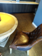
在本程式碼研究室中,您將建構應用程式,使用每個影格的原始深度圖片,對周遭世界進行幾何分析。這個應用程式將:
- 檢查目標裝置是否支援深度。
- 擷取每個相機影格的原始深度圖片。
- 將原始景深圖片重新投影成 3D 點,並根據信心和幾何圖形篩選這些點。
- 使用原始深度點雲層區隔感興趣的 3D 物件。
|
預告即將建構的內容。 |
注意:如果過程中遇到問題,請跳到最後一節查看疑難排解提示。
2. 必要條件
您需要使用特定的硬體和軟體,才能完成這個程式碼研究室。
硬體需求
- 支援 ARCore 的裝置 (已啟用 USB 偵錯功能),已透過 USB 傳輸線連接至您的開發機器。此裝置也必須支援 Depth API。
軟體需求
- ARCore SDK 1.31.0 以上版本。
- 已安裝 Android Studio (4.0.1 以上版本) 的開發機器。
3. 設定
設定開發機器
使用 USB 傳輸線將 ARCore 裝置連接至電腦。確認裝置允許 USB 偵錯。開啟終端機並執行 adb devices,如下所示:
adb devices

List of devices attached
<DEVICE_SERIAL_NUMBER>    device
<DEVICE_SERIAL_NUMBER>是裝置專屬的字串。繼續操作前,請確認每個裝置只有一部裝置。
下載並安裝程式碼
您可以複製存放區:
git clone https://github.com/googlecodelabs/arcore-rawdepthapi
或下載 ZIP 檔案並解壓縮:
請按照下列步驟開始使用程式碼。
- 啟動 Android Studio,然後選擇「Open an existing Android Studio project」。
- 前往您儲存原始深度 ZIP 檔案的本機目錄。
- 按兩下
arcore_rawdepthapi_codelab目錄。
arcore_rawdepthapi_codelab 目錄是包含多個模組的單一 Gradle 專案。如果 Android Studio 左上方的「Project」窗格未顯示在「Project」窗格中,請按一下下拉式選單中的「Projects」。
結果看起來會像這樣:
| 這項專案包含下列模組:
|
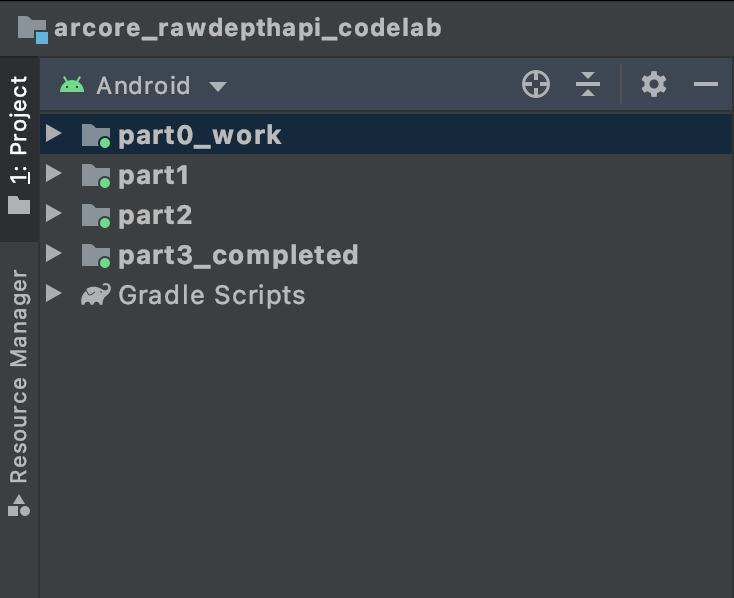
您將在 part0_work 模組中工作。另外,程式碼研究室的每個部分都有完整的解決方案。每個模組都是可建構的應用程式。
4. 執行範例應用程式
請按照下列步驟執行原始深度範例應用程式。
- 瀏覽至 [執行] >。執行...>‘part0_work'。
- 在「Select Deployment Target」對話方塊中,從「Connected Devices」清單中選取您的裝置,然後按一下「OK」。
Android Studio 會建構初始應用程式,並在您的裝置上執行。
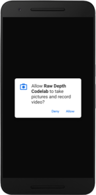
| 首次執行應用程式時,應用程式會要求 CAMERA 權限。輕觸「允許」即可繼續。 |
| 目前應用程式沒有任何作用。這是最基本的 AR 應用程式,用於顯示場景的相機畫面,但不會執行任何其他操作。現有程式碼類似於透過 ARCore SDK 發布的 Hello AR 範例。 |
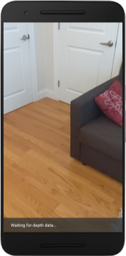
接下來,您將使用 Raw Depth API 擷取周圍場景的幾何圖形。
5. 設定原始 Depth API (第 1 部分)
確認目標裝置支援深度
並非所有支援 ARCore 的裝置都能執行 Depth API。請先確認目標裝置支援深度,再透過 RawDepthCodelabActivity.java 的 onResume() 函式 (此函式會建立新的工作階段) 為應用程式新增功能。
尋找現有代碼:
// Create the ARCore session.
session = new Session(/* context= */ this);
請更新應用程式,確保應用程式只能在支援 Depth API 的裝置上執行。
// Create the ARCore session.
session = new Session(/* context= */ this);
if (!session.isDepthModeSupported(Config.DepthMode.RAW_DEPTH_ONLY)) {
  message =
     "This device does not support the ARCore Raw Depth API. See" +
     "https://developers.google.com/ar/devices for
     a list of devices that do.";
}
啟用原始深度
「原始深度 API」提供未經平滑的深度圖片,以及一個對應的可信度圖片,其中含有原始深度圖片中每個像素的深度信心。在剛才修改的 try-catch 陳述式下方更新下列程式碼,即可啟用原始深度。
try {
  // ************ New code to add ***************
  // Enable raw depth estimation and auto focus mode while ARCore is running.
  Config config = session.getConfig();
  config.setDepthMode(Config.DepthMode.RAW_DEPTH_ONLY);
  config.setFocusMode(Config.FocusMode.AUTO);
  session.configure(config);
  // ************ End new code to add ***************
  session.resume();
} catch (CameraNotAvailableException e) {
  messageSnackbarHelper.showError(this, "Camera not available. Try restarting the app.");
  session = null;
  return;
}
現在 AR 工作階段已正確設定,應用程式可以使用深度相關功能。
呼叫深度 API
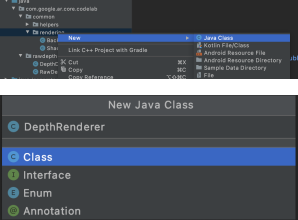
接下來,呼叫 Depth API 來擷取每個影格的深度圖片。透過建立新檔案,將深度資料封裝至新類別。對 rawdepth 資料夾按一下滑鼠右鍵,然後選取 New > Java Class。系統會建立空白檔案。將以下內容新增到這個類別:
src/main/java/com/google/ar/core/codelab/rawdepth/DepthData.java
package com.google.ar.core.codelab.rawdepth;

import android.media.Image;
import android.opengl.Matrix;

import com.google.ar.core.Anchor;
import com.google.ar.core.CameraIntrinsics;
import com.google.ar.core.Frame;
import com.google.ar.core.exceptions.NotYetAvailableException;

import java.nio.ByteBuffer;
import java.nio.ByteOrder;
import java.nio.FloatBuffer;
import java.nio.ShortBuffer;

/**
 * Convert depth data from ARCore depth images to 3D pointclouds. Points are added by calling the
 * Raw Depth API, and reprojected into 3D space.
 */
public class DepthData {
    public static final int FLOATS_PER_POINT = 4; // X,Y,Z,confidence.

}
這個類別可用來將深度圖片轉換為點雲端。Pointclouds 以清單形式呈現場景幾何圖形,每個點都有 3D 座標 (x, y, z) 和信賴值 (範圍從 0 到 1)。
新增呼叫,以便使用 Raw Depth API 填入這些值,方法是在類別底部新增 create() 方法。這個方法會查詢最新的深度和可信度圖片,儲存產生的點雲端。深度和可信度圖片將有相符的資料。
public static FloatBuffer create(Frame frame, Anchor cameraPoseAnchor) {
    try {
        Image depthImage = frame.acquireRawDepthImage16Bits();
        Image confidenceImage = frame.acquireRawDepthConfidenceImage();

        // Retrieve the intrinsic camera parameters corresponding to the depth image to
        // transform 2D depth pixels into 3D points. See more information about the depth values
        // at
        // https://developers.google.com/ar/develop/java/depth/overview#understand-depth-values.

        final CameraIntrinsics intrinsics = frame.getCamera().getTextureIntrinsics();
        float[] modelMatrix = new float[16];
        cameraPoseAnchor.getPose().toMatrix(modelMatrix, 0);
        final FloatBuffer points = convertRawDepthImagesTo3dPointBuffer(
                depthImage, confidenceImage, intrinsics, modelMatrix);

        depthImage.close();
        confidenceImage.close();

        return points;
    } catch (NotYetAvailableException e) {
        // This normally means that depth data is not available yet.
        // This is normal, so you don't have to spam the logcat with this.
    }
    return null;
}
|
|
|
|
|
|
|
|
程式碼也會儲存相機錨點,因此您可以呼叫輔助方法 convertRawDepthImagesTo3dPointBuffer(),將深度資訊轉換為世界座標。此輔助方法會擷取深度影像中的每個像素,並使用相機內建函式將深度投影到相對於相機的 3D 點。接著,使用相機錨點將該點的位置轉換為世界座標。每個存在的像素都會轉換為 3D 點 (以公尺為單位),並與信心值一起儲存。
將以下輔助方法新增至 DepthData.java:
/** Apply camera intrinsics to convert depth image into a 3D pointcloud. */
    private static FloatBuffer convertRawDepthImagesTo3dPointBuffer(
            Image depth, Image confidence, CameraIntrinsics cameraTextureIntrinsics, float[] modelMatrix) {
        // Java uses big endian so change the endianness to ensure
        // that the depth data is in the correct byte order.
        final Image.Plane depthImagePlane = depth.getPlanes()[0];
        ByteBuffer depthByteBufferOriginal = depthImagePlane.getBuffer();
        ByteBuffer depthByteBuffer = ByteBuffer.allocate(depthByteBufferOriginal.capacity());
        depthByteBuffer.order(ByteOrder.LITTLE_ENDIAN);
        while (depthByteBufferOriginal.hasRemaining()) {
            depthByteBuffer.put(depthByteBufferOriginal.get());
        }
        depthByteBuffer.rewind();
        ShortBuffer depthBuffer = depthByteBuffer.asShortBuffer();

        final Image.Plane confidenceImagePlane = confidence.getPlanes()[0];
        ByteBuffer confidenceBufferOriginal = confidenceImagePlane.getBuffer();
        ByteBuffer confidenceBuffer = ByteBuffer.allocate(confidenceBufferOriginal.capacity());
        confidenceBuffer.order(ByteOrder.LITTLE_ENDIAN);
        while (confidenceBufferOriginal.hasRemaining()) {
            confidenceBuffer.put(confidenceBufferOriginal.get());
        }
        confidenceBuffer.rewind();

        // To transform 2D depth pixels into 3D points, retrieve the intrinsic camera parameters
        // corresponding to the depth image. See more information about the depth values at
        // https://developers.google.com/ar/develop/java/depth/overview#understand-depth-values.
        final int[] intrinsicsDimensions = cameraTextureIntrinsics.getImageDimensions();
        final int depthWidth = depth.getWidth();
        final int depthHeight = depth.getHeight();
        final float fx =
                cameraTextureIntrinsics.getFocalLength()[0] * depthWidth / intrinsicsDimensions[0];
        final float fy =
                cameraTextureIntrinsics.getFocalLength()[1] * depthHeight / intrinsicsDimensions[1];
        final float cx =
                cameraTextureIntrinsics.getPrincipalPoint()[0] * depthWidth / intrinsicsDimensions[0];
        final float cy =
                cameraTextureIntrinsics.getPrincipalPoint()[1] * depthHeight / intrinsicsDimensions[1];

        // Allocate the destination point buffer. If the number of depth pixels is larger than
        // `maxNumberOfPointsToRender` we uniformly subsample. The raw depth image may have
        // different resolutions on different devices.
        final float maxNumberOfPointsToRender = 20000;
        int step = (int) Math.ceil(Math.sqrt(depthWidth * depthHeight / maxNumberOfPointsToRender));

        FloatBuffer points = FloatBuffer.allocate(depthWidth / step * depthHeight / step * FLOATS_PER_POINT);
        float[] pointCamera = new float[4];
        float[] pointWorld = new float[4];

        for (int y = 0; y < depthHeight; y += step) {
            for (int x = 0; x < depthWidth; x += step) {
                // Depth images are tightly packed, so it's OK to not use row and pixel strides.
                int depthMillimeters = depthBuffer.get(y * depthWidth + x); // Depth image pixels are in mm.
                if (depthMillimeters == 0) {
                    // Pixels with value zero are invalid, meaning depth estimates are missing from
                    // this location.
                    continue;
                }
                final float depthMeters = depthMillimeters / 1000.0f; // Depth image pixels are in mm.

                // Retrieve the confidence value for this pixel.
                final byte confidencePixelValue =
                        confidenceBuffer.get(
                                y * confidenceImagePlane.getRowStride()
                                        + x * confidenceImagePlane.getPixelStride());
                final float confidenceNormalized = ((float) (confidencePixelValue & 0xff)) / 255.0f;

                // Unproject the depth into a 3D point in camera coordinates.
                pointCamera[0] = depthMeters * (x - cx) / fx;
                pointCamera[1] = depthMeters * (cy - y) / fy;
                pointCamera[2] = -depthMeters;
                pointCamera[3] = 1;

                // Apply model matrix to transform point into world coordinates.
                Matrix.multiplyMV(pointWorld, 0, modelMatrix, 0, pointCamera, 0);
                points.put(pointWorld[0]); // X.
                points.put(pointWorld[1]); // Y.
                points.put(pointWorld[2]); // Z.
                points.put(confidenceNormalized);
            }
        }

        points.rewind();
        return points;
    }
取得每個影格的最新原始深度資料
請修改應用程式以擷取深度資訊,並將其與各個姿勢的世界座標對齊。
在 RawDepthCodelabActivity.java 的 onDrawFrame() 方法中,找出現有行:
Frame frame = session.update();
Camera camera = frame.getCamera();

// If the frame is ready, render the camera preview image to the GL surface.
backgroundRenderer.draw(frame);
在下方加入以下指令行:
// Retrieve the depth data for this frame.
FloatBuffer points = DepthData.create(frame, session.createAnchor(camera.getPose()));
if (points == null) {
  return;
}

if (messageSnackbarHelper.isShowing() && points != null) {
  messageSnackbarHelper.hide(this);
}
6. 轉譯深度資料 (第 2 部分)
既然您已經有深度點雲可以操作,接著就來看看在畫面上顯示的資料。
新增轉譯器,以視覺化方式呈現深度點
新增轉譯器,以視覺化方式呈現深度點。
首先,新增要包含轉譯邏輯的新類別。此類別會執行 OpenGL 作業,初始化著色器,以視覺化方式呈現深度點雲端。
| 新增 DepthRenderer 類別
|
使用下列程式碼填入這個類別:
src/main/java/com/google/ar/core/codelab/common/rendering/DepthRenderer.java
package com.google.ar.core.codelab.common.rendering;

import android.content.Context;
import android.opengl.GLES20;
import android.opengl.Matrix;

import com.google.ar.core.Camera;
import com.google.ar.core.codelab.rawdepth.DepthData;

import java.io.IOException;
import java.nio.FloatBuffer;

public class DepthRenderer {
    private static final String TAG = DepthRenderer.class.getSimpleName();

    // Shader names.
    private static final String VERTEX_SHADER_NAME = "shaders/depth_point_cloud.vert";
    private static final String FRAGMENT_SHADER_NAME = "shaders/depth_point_cloud.frag";

    public static final int BYTES_PER_FLOAT = Float.SIZE / 8;
    private static final int BYTES_PER_POINT = BYTES_PER_FLOAT * DepthData.FLOATS_PER_POINT;
    private static final int INITIAL_BUFFER_POINTS = 1000;

    private int arrayBuffer;
    private int arrayBufferSize;

    private int programName;
    private int positionAttribute;
    private int modelViewProjectionUniform;
    private int pointSizeUniform;

    private int numPoints = 0;

    public DepthRenderer() {}

    public void createOnGlThread(Context context) throws IOException {
        ShaderUtil.checkGLError(TAG, "Bind");

        int[] buffers = new int[1];
        GLES20.glGenBuffers(1, buffers, 0);
        arrayBuffer = buffers[0];
        GLES20.glBindBuffer(GLES20.GL_ARRAY_BUFFER, arrayBuffer);

        arrayBufferSize = INITIAL_BUFFER_POINTS * BYTES_PER_POINT;
        GLES20.glBufferData(GLES20.GL_ARRAY_BUFFER, arrayBufferSize, null, GLES20.GL_DYNAMIC_DRAW);
        GLES20.glBindBuffer(GLES20.GL_ARRAY_BUFFER, 0);

        ShaderUtil.checkGLError(TAG, "Create");

        int vertexShader =
                ShaderUtil.loadGLShader(TAG, context, GLES20.GL_VERTEX_SHADER, VERTEX_SHADER_NAME);
        int fragmentShader =
                ShaderUtil.loadGLShader(TAG, context, GLES20.GL_FRAGMENT_SHADER, FRAGMENT_SHADER_NAME);

        programName = GLES20.glCreateProgram();
        GLES20.glAttachShader(programName, vertexShader);
        GLES20.glAttachShader(programName, fragmentShader);
        GLES20.glLinkProgram(programName);
        GLES20.glUseProgram(programName);

        ShaderUtil.checkGLError(TAG, "Program");

        positionAttribute = GLES20.glGetAttribLocation(programName, "a_Position");
        modelViewProjectionUniform = GLES20.glGetUniformLocation(programName, "u_ModelViewProjection");
        // Sets the point size, in pixels.
        pointSizeUniform = GLES20.glGetUniformLocation(programName, "u_PointSize");

        ShaderUtil.checkGLError(TAG, "Init complete");
    }
}
轉譯深度資料
接著,請提供轉譯著色器的來源。在 DepthRenderer 類別底部新增下列 update() 方法。這個方法會將最新的深度資訊做為輸入資料,並將點雲端資料複製到 GPU。
    /**
     * Update the OpenGL buffer contents to the provided point. Repeated calls with the same point
     * cloud will be ignored.
     */
    public void update(FloatBuffer points) {
        ShaderUtil.checkGLError(TAG, "Update");
        GLES20.glBindBuffer(GLES20.GL_ARRAY_BUFFER, arrayBuffer);

        // If the array buffer is not large enough to fit the new point cloud, resize it.
        points.rewind();
        numPoints = points.remaining() / DepthData.FLOATS_PER_POINT;
        if (numPoints * BYTES_PER_POINT > arrayBufferSize) {
            while (numPoints * BYTES_PER_POINT > arrayBufferSize) {
                arrayBufferSize *= 2;
            }
            GLES20.glBufferData(GLES20.GL_ARRAY_BUFFER, arrayBufferSize, null, GLES20.GL_DYNAMIC_DRAW);
        }

        GLES20.glBufferSubData(
                GLES20.GL_ARRAY_BUFFER, 0, numPoints * BYTES_PER_POINT, points);
        GLES20.glBindBuffer(GLES20.GL_ARRAY_BUFFER, 0);

        ShaderUtil.checkGLError(TAG, "Update complete");
    }
在 DepthRenderer 類別底部新增 draw() 方法,將最新資料繪製到畫面。這個方法能擷取 3D Pointcloud 資訊,並投影回相機檢視畫面,以便在螢幕上呈現。
    /** Render the point cloud. The ARCore point cloud is given in world space. */
    public void draw(Camera camera) {
        float[] projectionMatrix = new float[16];
        camera.getProjectionMatrix(projectionMatrix, 0, 0.1f, 100.0f);
        float[] viewMatrix = new float[16];
        camera.getViewMatrix(viewMatrix, 0);
        float[] viewProjection = new float[16];
        Matrix.multiplyMM(viewProjection, 0, projectionMatrix, 0, viewMatrix, 0);

        ShaderUtil.checkGLError(TAG, "Draw");

        GLES20.glUseProgram(programName);
        GLES20.glEnableVertexAttribArray(positionAttribute);
        GLES20.glBindBuffer(GLES20.GL_ARRAY_BUFFER, arrayBuffer);
        GLES20.glVertexAttribPointer(positionAttribute, 4, GLES20.GL_FLOAT, false, BYTES_PER_POINT, 0);
        GLES20.glUniformMatrix4fv(modelViewProjectionUniform, 1, false, viewProjection, 0);
        // Set point size to 5 pixels.
        GLES20.glUniform1f(pointSizeUniform, 5.0f);

        GLES20.glDrawArrays(GLES20.GL_POINTS, 0, numPoints);
        GLES20.glDisableVertexAttribArray(positionAttribute);
        GLES20.glBindBuffer(GLES20.GL_ARRAY_BUFFER, 0);

        ShaderUtil.checkGLError(TAG, "Draw complete");
    }
您可以使用 pointSizeUniform 變數,將點大小設為不同的大小 (以像素為單位)。在範例應用程式中,pointSizeUniform 已設為 5 像素。
新增著色器
您可以透過多種方式查看應用程式的深度及顯示深度資料。您將新增幾個著色器,並建立簡單的顏色對應視覺化呈現。
在 src/main/assets/shaders/ 目錄中新增 .vert 和 .frag 著色器。
| 新增 .vert 著色器在 Android Studio 中:
|
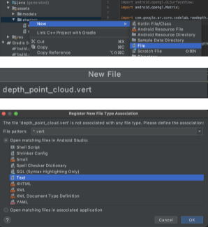
在新的 .vert 檔案中加入下列程式碼:
src/main/assets/shaders/depth_point_cloud.vert
uniform mat4 u_ModelViewProjection;
uniform float u_PointSize;

attribute vec4 a_Position;

varying vec4 v_Color;

// Return an interpolated color in a 6 degree polynomial interpolation.
vec3 GetPolynomialColor(in float x,
  in vec4 kRedVec4, in vec4 kGreenVec4, in vec4 kBlueVec4,
  in vec2 kRedVec2, in vec2 kGreenVec2, in vec2 kBlueVec2) {
  // Moves the color space a little bit to avoid pure red.
  // Removes this line for more contrast.
  x = clamp(x * 0.9 + 0.03, 0.0, 1.0);
  vec4 v4 = vec4(1.0, x, x * x, x * x * x);
  vec2 v2 = v4.zw * v4.z;
  return vec3(
    dot(v4, kRedVec4) + dot(v2, kRedVec2),
    dot(v4, kGreenVec4) + dot(v2, kGreenVec2),
    dot(v4, kBlueVec4) + dot(v2, kBlueVec2)
  );
}

// Return a smooth Percept colormap based upon the Turbo colormap.
vec3 PerceptColormap(in float x) {
  const vec4 kRedVec4 = vec4(0.55305649, 3.00913185, -5.46192616, -11.11819092);
  const vec4 kGreenVec4 = vec4(0.16207513, 0.17712472, 15.24091500, -36.50657960);
  const vec4 kBlueVec4 = vec4(-0.05195877, 5.18000081, -30.94853351, 81.96403246);
  const vec2 kRedVec2 = vec2(27.81927491, -14.87899417);
  const vec2 kGreenVec2 = vec2(25.95549545, -5.02738237);
  const vec2 kBlueVec2 = vec2(-86.53476570, 30.23299484);
  const float kInvalidDepthThreshold = 0.01;
  return step(kInvalidDepthThreshold, x) *
         GetPolynomialColor(x, kRedVec4, kGreenVec4, kBlueVec4,
                            kRedVec2, kGreenVec2, kBlueVec2);
}

void main() {
   // Color the pointcloud by height.
   float kMinHeightMeters = -2.0f;
   float kMaxHeightMeters = 2.0f;
   float normalizedHeight = clamp((a_Position.y - kMinHeightMeters) / (kMaxHeightMeters - kMinHeightMeters), 0.0, 1.0);
   v_Color = vec4(PerceptColormap(normalizedHeight), 1.0);
   gl_Position = u_ModelViewProjection * vec4(a_Position.xyz, 1.0);
   gl_PointSize = u_PointSize;
}
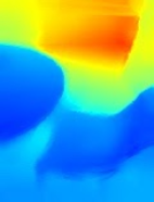
此著色器使用Turbo 色彩圖改善視覺化效果。這個檔案會執行下列步驟:
- 擷取每個點的高度 (世界座標中的 Y 軸)。
- 計算與該高度相關聯的顏色 (red=low、blue=high)。
- 計算每個點的螢幕位置。
- 設定每個點的大小 (以像素為單位),如
DepthRenderer.update()方法所定義。
在相同的目錄中建立片段著色器並命名為 depth_point_cloud.frag,並重複本節中的相同步驟。
接著,請將下列程式碼新增至這個新檔案,將每個點算繪為統一顏色的單一頂點 (如頂點著色器中所定義)。
src/main/assets/shaders/depth_point_cloud.frag
precision mediump float;
varying vec4 v_Color;

void main() {
    gl_FragColor = v_Color;
}
如要套用此算繪,請在 RawDepthCodelabActivity 中新增對 DepthRenderer 類別的呼叫。
src/main/java/com/google/ar/core/codelab/common/rendering/RawDepthCodelabActivity.java
import com.google.ar.core.codelab.common.rendering.DepthRenderer;
在課程頂端的 backgroundRenderer 旁邊新增私人成員。
private final DepthRenderer depthRenderer = new DepthRenderer();
您必須在 RawDepthCodelabActivity.onSurfaceCreated() 中初始化 depthRenderer,就像在現有的 backgroundRenderer 中一樣。
depthRenderer.createOnGlThread(/*context=*/ this);
在 onDrawFrame 中的 try-catch 區塊結尾加入下列程式碼,即可顯示目前影格的最新深度。
// Visualize depth points.
depthRenderer.update(points);
depthRenderer.draw(camera);
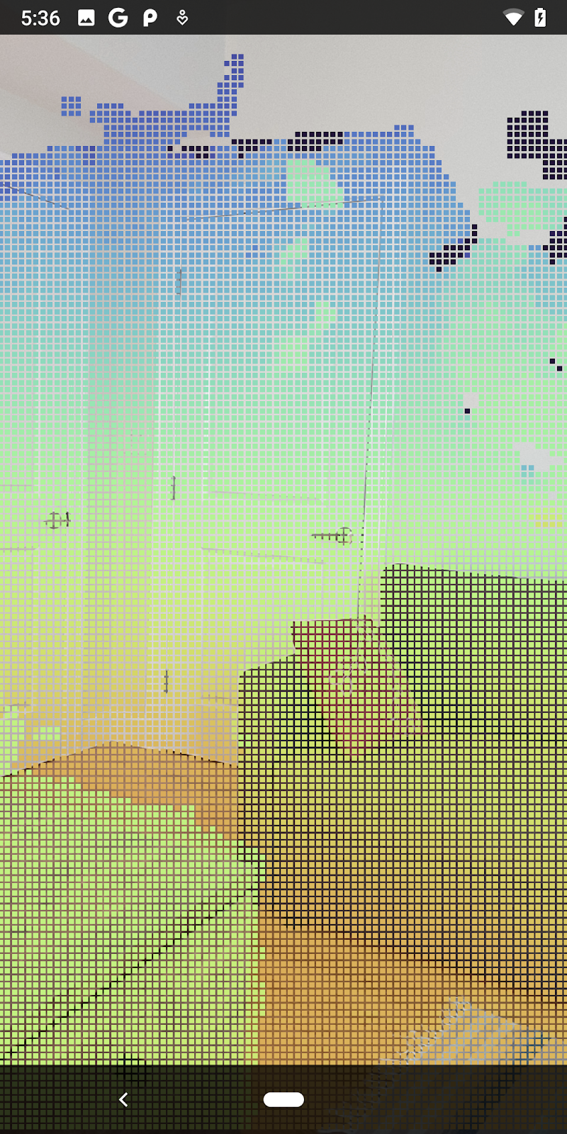
變更後,應用程式現在應可成功建構並顯示深度點雲。
| 原始深度點雲端視覺化範例
|

7. 分析 3D 點雲 (第 3 部分)
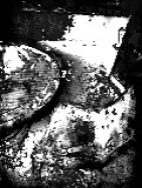
確認 AR 工作階段中存在深度資料後,就可以分析這些資料。分析深度的重要工具是每個像素的「可信度」值。運用信心值分析 3D 點雲。
使低可信度像素失效
您已擷取每個深度像素的可信度值,並將其與 DepthData 內的每一個點一起儲存,但尚未使用。
confidenceNormalized 的值介於 0 到 1 之間,0 表示可信度不足,1 表示完全有信心。修改 DepthData 類別中的 convertRawDepthImagesTo3dPointBuffer() 方法,避免儲存可信度過低的像素。
final float confidenceNormalized = ((float) (confidencePixelValue & 0xff)) / 255.0f;

// ******** New code to add ************
if (confidenceNormalized < 0.3) {
   // Ignores "low-confidence" pixels.
   continue;
}
// ******** End of new code to add *********
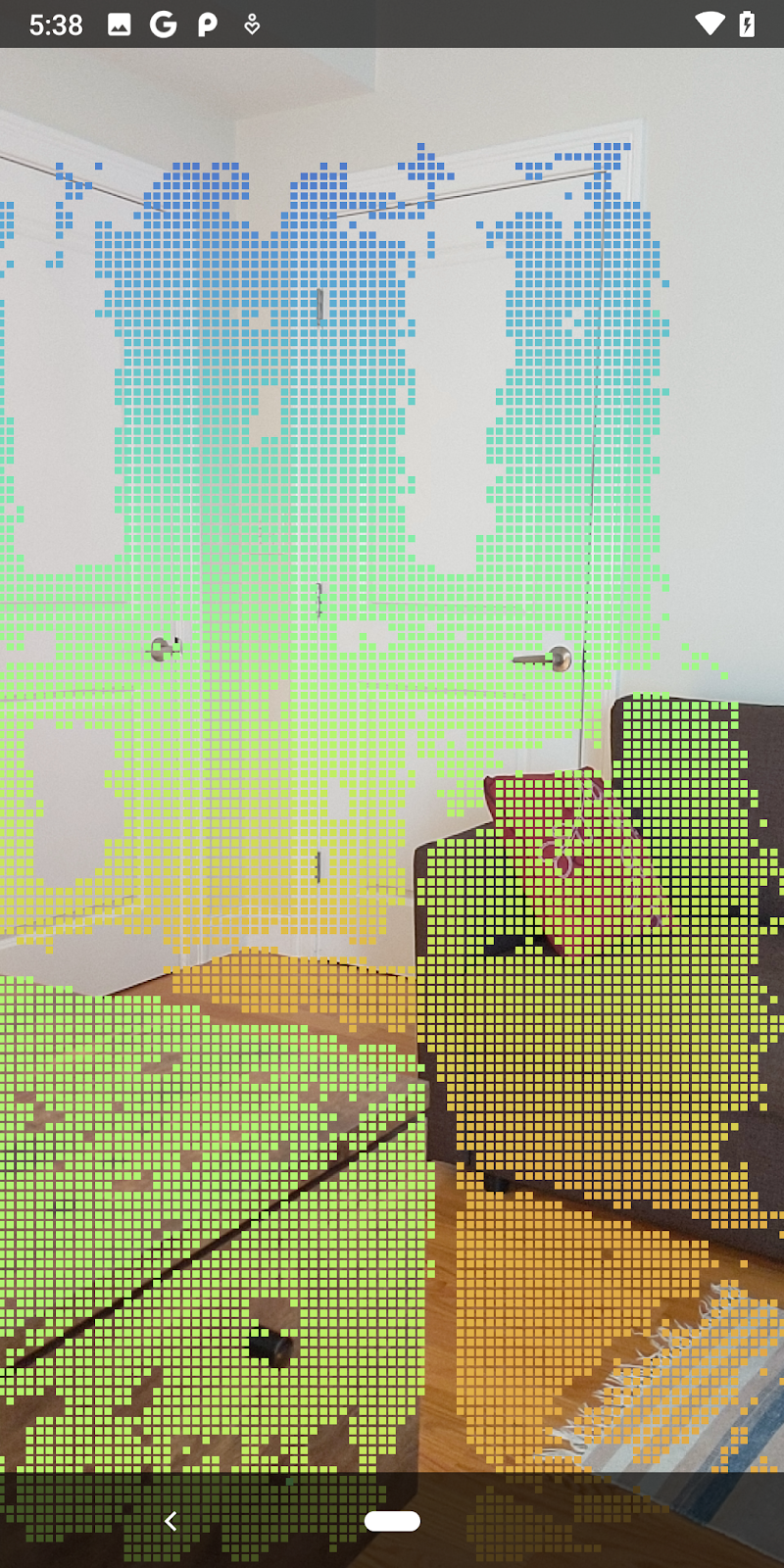
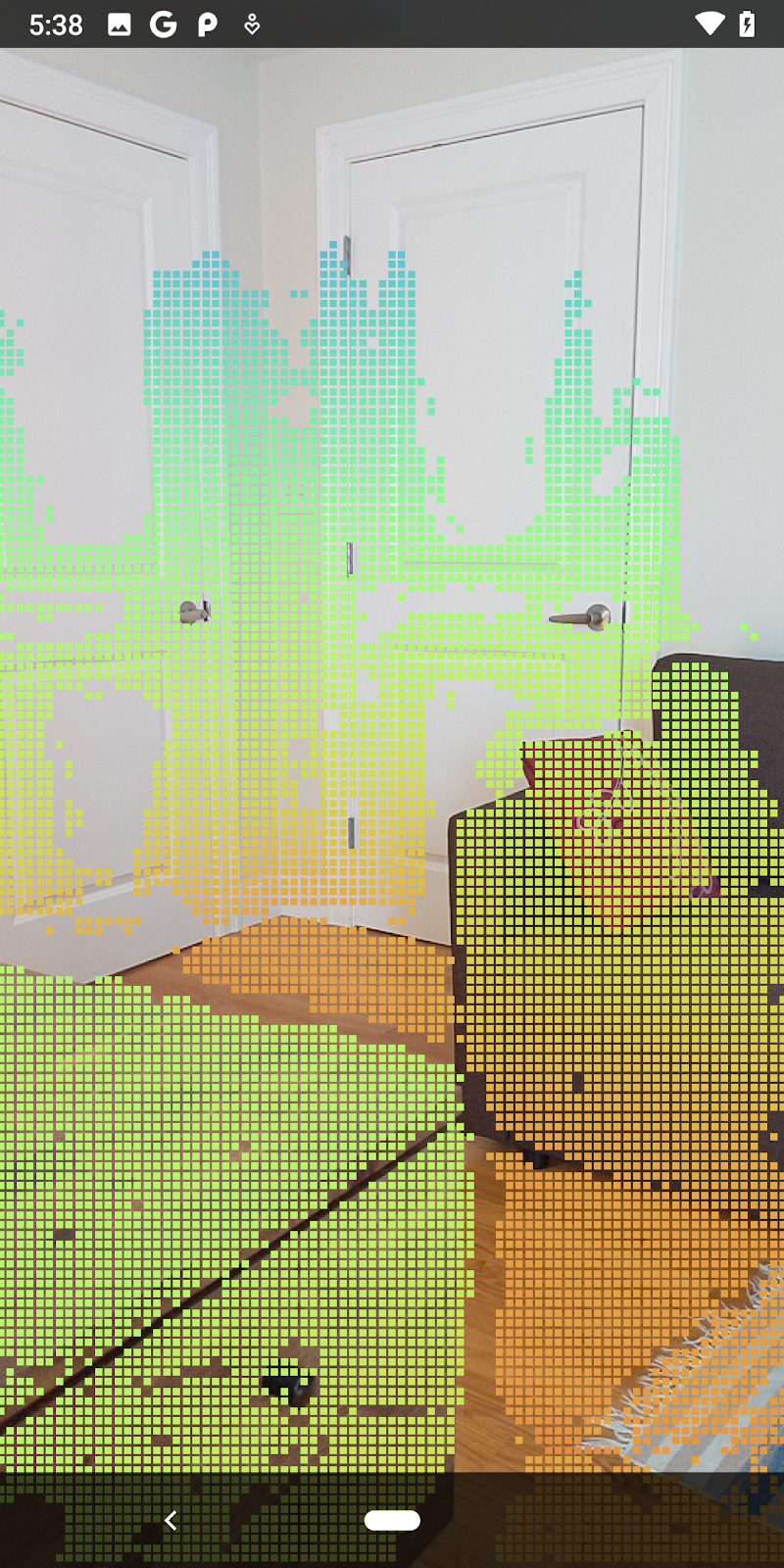
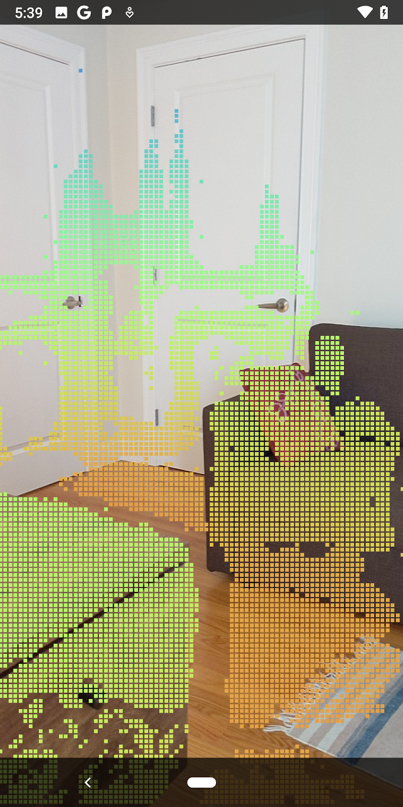
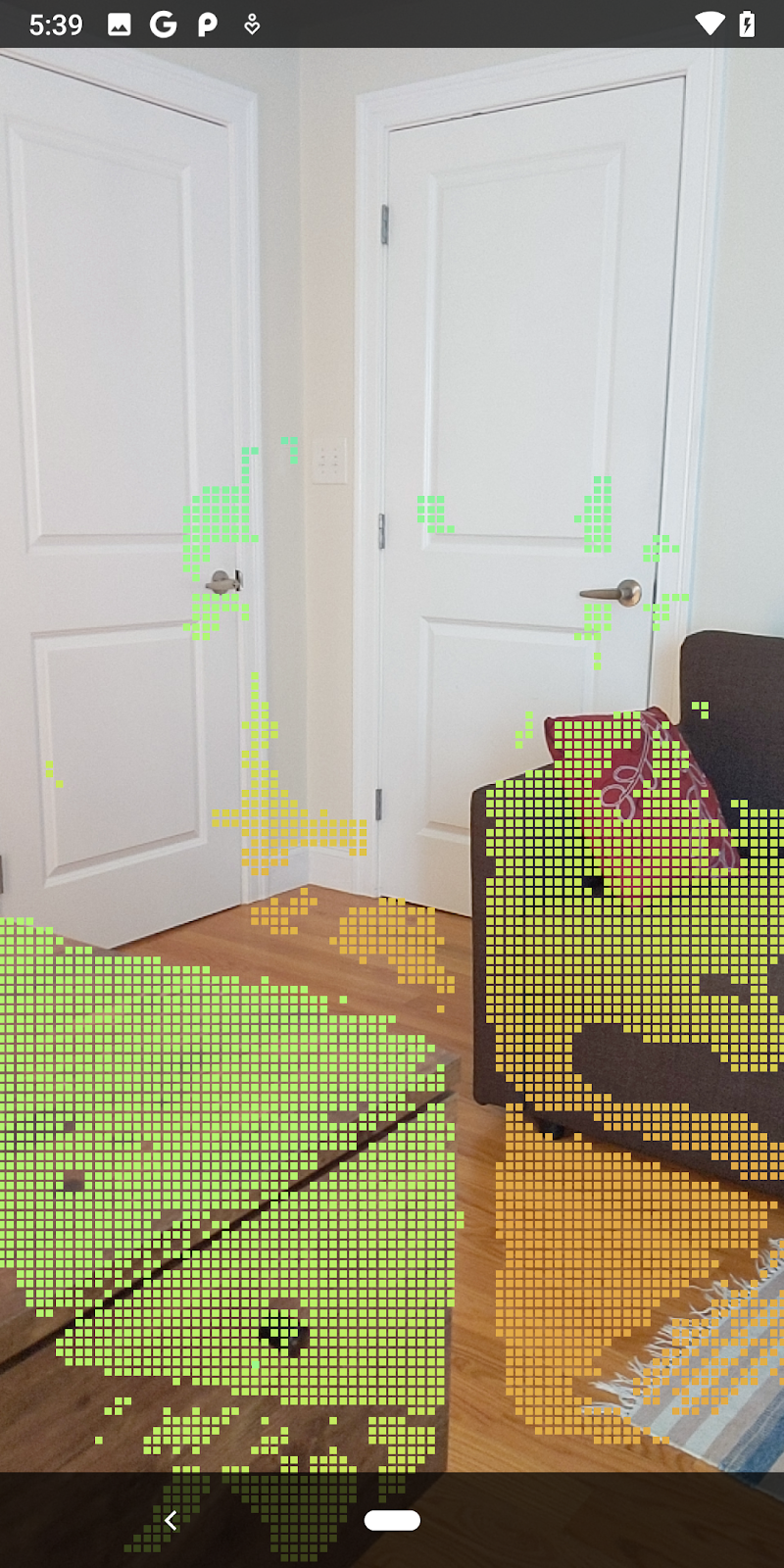
試著針對信賴水準設定不同的門檻,瞭解各層級保留了多少深度點。
|
|
|
|
|
信賴水準 >= 0.1 | 信賴水準 >= 0.3 | 信賴水準 >= 0.5 | 信賴水準 >= 0.7 | 信賴水準 >= 0.9 |
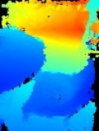
按照距離篩選像素
您也可以依距離篩選深度像素。下方步驟來處理鏡頭靠近相機的幾何圖形。為提高效能,您可以忽略距離太遠的點。
使用下列指令更新您剛剛新增的可信度檢查程式碼:
src/main/java/com/google/ar/core/codelab/rawdepth/DepthData.java
if (confidenceNormalized < 0.3 || depthMeters > 1.5) {
    // Ignore "low-confidence" pixels or depth that is too far away.
   continue;
 }
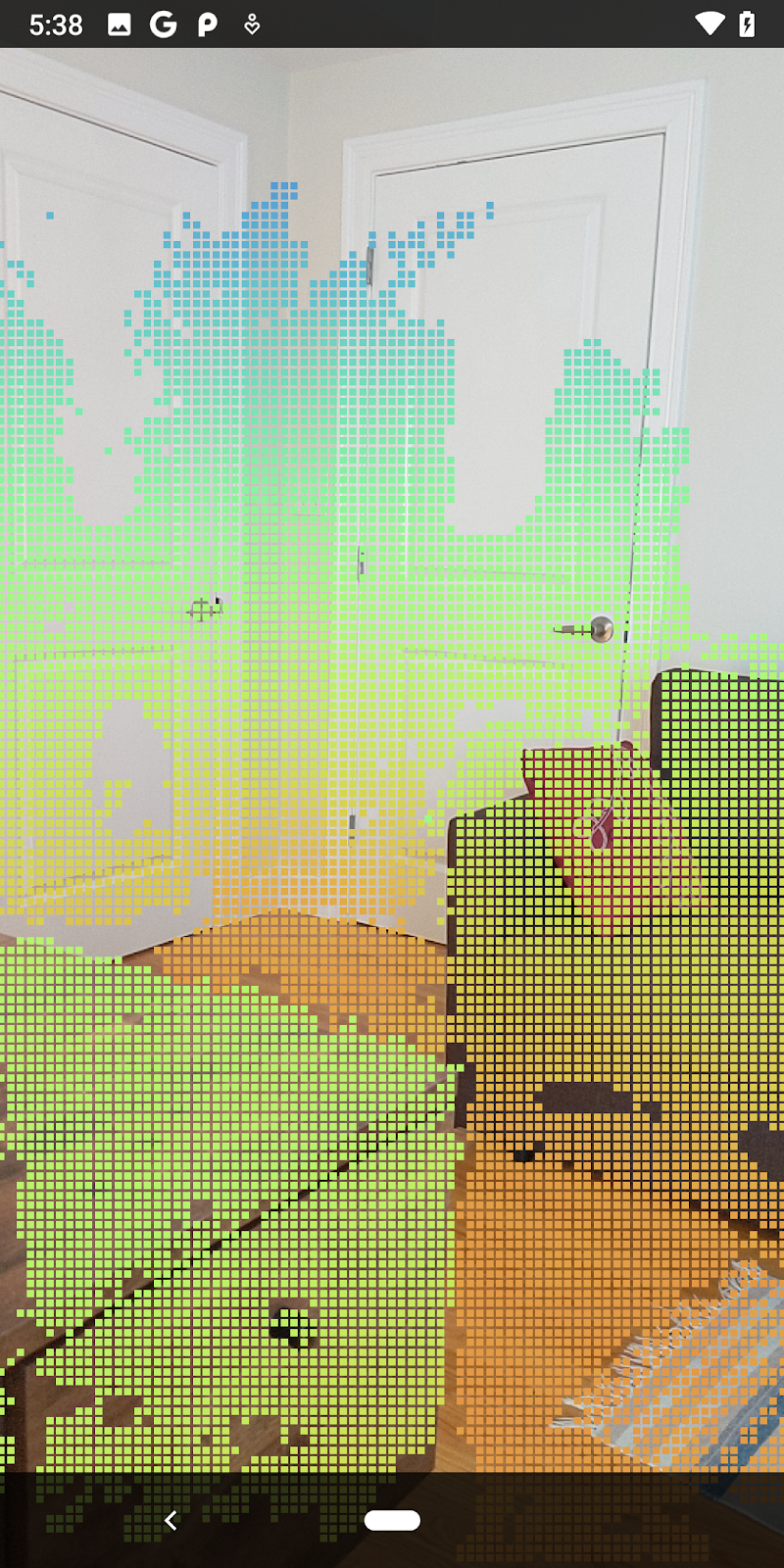
現在你只會看到可信度高和成交點。
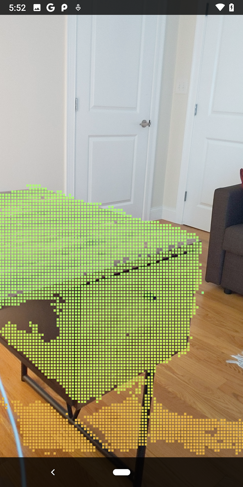
| 距離篩選將點雲限制在相機距離 1.5 公尺以內。 |
比較 3D 點和平面
您可以比較幾何圖形 3D 點和平面,並使用這些點來篩選彼此,例如移除接近觀察到 AR 平面的點。
這個步驟只會保留「非平面」通常代表環境物件表面的 點。將 filterUsingPlanes() 方法新增至 DepthData 類別底部。這個方法會反覆檢查現有點,針對每個平面檢查每個點,並停用任何太接近 AR 平面的任何點,留下會醒目顯示場景中物件的非平面區域。
src/main/java/com/google/ar/core/codelab/rawdepth/DepthData.java
    public static void filterUsingPlanes(FloatBuffer points, Collection<Plane> allPlanes) {
        float[] planeNormal = new float[3];

        // Allocate the output buffer.
        int numPoints = points.remaining() / DepthData.FLOATS_PER_POINT;

        // Check each plane against each point.
        for (Plane plane : allPlanes) {
            if (plane.getTrackingState() != TrackingState.TRACKING || plane.getSubsumedBy() != null) {
                continue;
            }

            // Compute the normal vector of the plane.
            Pose planePose = plane.getCenterPose();
            planePose.getTransformedAxis(1, 1.0f, planeNormal, 0);

            // Filter points that are too close to the plane.
            for (int index = 0; index < numPoints; ++index) {
                // Retrieves the next point.
                final float x = points.get(FLOATS_PER_POINT * index);
                final float y = points.get(FLOATS_PER_POINT * index + 1);
                final float z = points.get(FLOATS_PER_POINT * index + 2);

                // Transform point to be in world coordinates, to match plane info.
                float distance = (x - planePose.tx()) * planeNormal[0]
                        + (y - planePose.ty()) * planeNormal[1]
                        + (z - planePose.tz()) * planeNormal[2];
                // Controls the size of objects detected.
                // Smaller values mean smaller objects will be kept.
                // Larger values will only allow detection of larger objects, but also helps reduce noise.
                if (Math.abs(distance) > 0.03) {
                    continue;  // Keep this point, since it's far enough away from the plane.
                }

                // Invalidate points that are too close to planar surfaces.
                points.put(FLOATS_PER_POINT * index, 0);
                points.put(FLOATS_PER_POINT * index + 1, 0);
                points.put(FLOATS_PER_POINT * index + 2, 0);
                points.put(FLOATS_PER_POINT * index + 3, 0);
            }
        }
    }
您可以在 onDrawFrame 方法中將此方法新增至 RawDepthCodelabActivity:
//  ********** New code to add ************
  // Filter the depth data.
  DepthData.filterUsingPlanes(points, session.getAllTrackables(Plane.class));
//  ********** End new code to add *******

  // Visualize depth points.
  depthRenderer.update(points);
  depthRenderer.draw(camera);
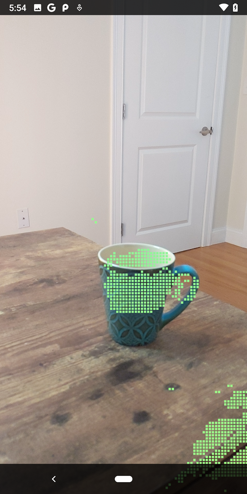
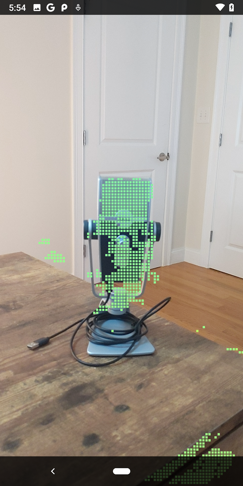
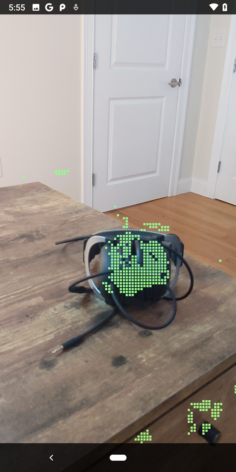
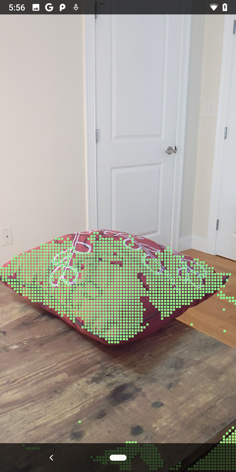
現在執行程式碼研究室會產生一部分的資料點。這些點代表場景中的物件,並忽略物件靜止所在的平坦表面。只要將這些資料分群,即可使用這些資料估算物件的大小和位置。
|
|
|
|
杯茶 | 麥克風 | 耳罩式耳機 | 枕頭 |
分群點
本程式碼研究室包含非常簡單的PointCloud 叢集演算法。更新程式碼研究室,將擷取的 Pointcloud 歸類為由軸對齊的定界框定義的叢集。
src/main/java/com/google/ar/core/codelab/rawdepth/RawDepthCodelabActivity.java
import com.google.ar.core.codelab.common.helpers.AABB;
import com.google.ar.core.codelab.common.helpers.PointClusteringHelper;
import com.google.ar.core.codelab.common.rendering.BoxRenderer;
import java.util.List;
在檔案頂端和其他轉譯器,為這個類別新增 BoxRenderer。
private final BoxRenderer boxRenderer = new BoxRenderer();
在 onSurfaceCreated() 方法中,將以下內容與其他轉譯器一起新增:
boxRenderer.createOnGlThread(/*context=*/this);
最後,將下列程式碼新增至 RawDepthCodelabActivity 中的 onDrawFrame(),將擷取的點雲分組至叢集,並將結果算繪為軸對齊的定界框。
      // Visualize depth points.
      depthRenderer.update(points);
      depthRenderer.draw(camera);

// ************ New code to add ***************

      // Draw boxes around clusters of points.
      PointClusteringHelper clusteringHelper = new PointClusteringHelper(points);
      List<AABB> clusters = clusteringHelper.findClusters();
      for (AABB aabb : clusters) {
        boxRenderer.draw(aabb, camera);
      }

// ************ End new code to add ***************
|
|
|
|
杯茶 | 麥克風 | 耳罩式耳機 | 枕頭 |
您現在可以透過 ARCore 工作階段擷取原始深度、將深度資訊轉換為 3D 點雲,並針對這些點執行基本的篩選和算繪作業。
8. Build-Run-Test
建構、執行及測試應用程式。
建構並執行應用程式
請按照下列步驟建構並執行應用程式:
- 透過 USB 插入支援 ARCore 的裝置。
- 使用選單列中的 ► 按鈕執行專案。
- 等待應用程式建構並部署至您的裝置。
首次嘗試在裝置上部署應用程式時,您必須
允許 USB 偵錯
應用程式。選取「確定」即可繼續操作。
首次在裝置上執行應用程式時,系統會詢問該應用程式是否有權使用裝置相機。您必須授予存取權,才能繼續使用 AR 功能。
測試應用程式
執行應用程式時,你可以按住裝置、在空間中四處移動,然後慢慢掃描區域,藉此測試應用程式的基本行為。請試著收集至少 10 秒的資料,並從多方向掃描該區域,再前往下一個步驟。
9. 恭喜
恭喜!你使用 Google 的 ARCore Raw Depth API,成功建構並執行第一個深度式擴增實境應用程式。我們很期待看到您打造的作品!
10. 疑難排解
設定開發用的 Android 裝置
- 使用 USB 傳輸線將裝置連接至您開發的機器上。如果您是使用 Windows 進行開發,可能需要為裝置安裝合適的 USB 驅動程式。
- 在「開發人員選項」視窗中按照下列步驟啟用「USB 偵錯」:
- 開啟「設定」應用程式。
- 如果您的裝置使用 Android 8.0 以上版本,請選取「系統」。
- 捲動至底部,然後選取「關於手機」。
- 捲動至底部,然後輕觸版本號碼七次。
- 返回上一個畫面,捲動至底部,然後輕觸「開發人員選項」。
- 在「開發人員選項」視窗中,向下捲動並啟用「USB 偵錯」。
如要進一步瞭解這項程序,請前往 Google 的 Android 開發人員網站。
與授權相關的建構錯誤
如果發生與授權 (Failed to install the following Android SDK packages as some licences have not been accepted) 相關的版本失敗,您可以使用下列指令來查看並接受這些授權:
cd <path to Android SDK>
tools/bin/sdkmanager --licenses