
1. 소개
ARCore는 휴대기기에서 증강 현실(AR) 앱을 빌드할 수 있는 플랫폼입니다. Google의 ARCore Depth API는 ARCore 세션의 각 프레임에 대한 심도 이미지에 대한 액세스를 제공합니다. 깊이 이미지의 각 픽셀은 카메라에서 환경까지의 거리 측정값을 제공합니다.
Raw Depth API는 결과를 매끄럽고 보간하도록 설계된 화면 공간 필터링 작업을 통해 전달되지 않는 깊이 이미지를 제공합니다. 이러한 값은 기하학적으로는 더 정확하지만, 누락된 데이터가 포함되어 있을 수 있고 연결된 카메라 이미지와의 정렬이 떨어질 수 있습니다.
이 Codelab에서는 Raw Depth API를 사용하여 장면의 3D 도형 분석을 실행하는 방법을 보여줍니다. 원시 깊이 데이터를 사용하여 세계의 도형을 감지하고 시각화하는 간단한 AR 지원 앱을 빌드합니다.
Depth 및 Raw Depth API는 ARCore 지원 기기의 하위 집합에서만 지원됩니다. Depth API는 Android에서만 사용할 수 있습니다.
빌드할 항목
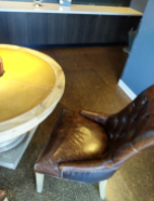
이 Codelab에서는 각 프레임에 원본 깊이 이미지를 사용하여 주변 세계의 기하학적 분석을 실행하는 앱을 빌드합니다. 이 앱은 다음 작업을 실행합니다.
- 대상 기기에서 심도를 지원하는지 확인합니다.
- 각 카메라 프레임의 원본 깊이 이미지를 가져옵니다.
- 원본 깊이 이미지를 3D 지점으로 다시 투영하고 신뢰도와 도형을 기반으로 해당 지점을 필터링합니다.
- 원본 심도 포인트 클라우드를 사용하여 관심 있는 3D 객체를 세분화합니다.
|
빌드할 항목의 미리보기 |
참고: 도중에 문제가 발생하면 마지막 섹션으로 이동하여 몇 가지 문제 해결 도움말을 확인하세요.
2. 기본 요건
이 Codelab을 완료하려면 특정 하드웨어와 소프트웨어가 필요합니다.
하드웨어 요구사항
- USB 디버깅이 사용 설정된 ARCore 지원 기기(USB 케이블을 통해 개발 머신에 연결되어 있어야 함) 이 기기는 Depth API도 지원해야 합니다.
소프트웨어 요구사항
- ARCore SDK 1.31.0 이상
- Android 스튜디오 (v4.0.1 이상)가 설치된 개발 머신
3. 설정
개발 머신 설정
USB 케이블을 통해 ARCore 기기를 컴퓨터에 연결합니다. 기기에서 USB 디버깅을 허용하는지 확인합니다. 터미널을 열고 아래와 같이 adb devices를 실행합니다.
adb devices

List of devices attached
<DEVICE_SERIAL_NUMBER>    device
<DEVICE_SERIAL_NUMBER>은 기기의 고유한 문자열입니다. 계속하기 전에 정확히 하나의 기기가 표시되는지 확인하세요.
코드 다운로드 및 설치하기
저장소를 클론할 수 있습니다.
git clone https://github.com/googlecodelabs/arcore-rawdepthapi
또는 ZIP 파일을 다운로드하고 압축을 풉니다.
코드 작업을 시작하려면 다음 단계를 따르세요.
- Android 스튜디오를 시작하고 Open an existing Android Studio project를 선택합니다.
- Raw Depth ZIP 파일을 저장한 로컬 디렉터리로 이동합니다.
arcore_rawdepthapi_codelab디렉터리를 더블클릭합니다.
arcore_rawdepthapi_codelab 디렉터리는 여러 모듈이 있는 단일 Gradle 프로젝트입니다. Android 스튜디오의 왼쪽 상단에 있는 Project 창이 아직 Project 창에 표시되지 않은 경우 드롭다운 메뉴에서 Projects를 클릭합니다.
다음과 같은 결과가 표시됩니다.
| 이 프로젝트에 있는 모듈은 다음과 같습니다.
|
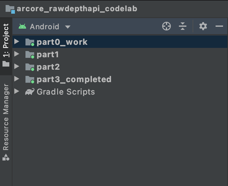
part0_work 모듈에서 작업하게 됩니다. Codelab의 각 부분에 관한 완전한 해결책도 있습니다. 각 모듈은 빌드 가능한 앱입니다.
4. 시작 앱 실행
Raw Depth 시작 앱을 실행하려면 다음 단계를 따르세요.
- 실행 > 실행... > ‘part0_work'를 클릭합니다.
- Select Deployment Target 대화상자의 Connected Devices 목록에서 기기를 선택하고 OK를 클릭합니다.
Android 스튜디오가 기기에서 초기 앱을 빌드하고 실행합니다.
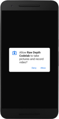
| 앱을 처음 실행하면 카메라 권한을 요청하는 메시지가 나타납니다. 계속하려면 허용을 탭합니다. |
| 현재 앱은 아무 작업도 하지 않습니다.이 앱은 가장 기본적인 AR 애플리케이션으로 장면의 카메라 뷰를 표시하지만 다른 작업은 수행하지 않습니다.기존 코드는 ARCore SDK로 게시된 Hello AR 샘플과 유사합니다. |
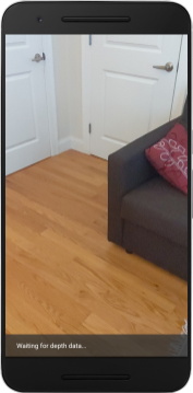
다음으로 Raw Depth API를 사용하여 주변 장면의 도형을 가져옵니다.
5. Raw Depth API 설정 (1부)
대상 기기가 깊이를 지원하는지 확인
일부 ARCore 지원 기기는 Depth API를 실행할 수 없습니다. 새 세션이 생성되는 RawDepthCodelabActivity.java의 onResume() 함수 내에서 앱에 기능을 추가하기 전에 대상 기기가 깊이를 지원하는지 확인하세요.
기존 코드를 찾습니다.
// Create the ARCore session.
session = new Session(/* context= */ this);
애플리케이션이 Depth API를 지원할 수 있는 기기에서만 실행되도록 하도록 업데이트합니다.
// Create the ARCore session.
session = new Session(/* context= */ this);
if (!session.isDepthModeSupported(Config.DepthMode.RAW_DEPTH_ONLY)) {
  message =
     "This device does not support the ARCore Raw Depth API. See" +
     "https://developers.google.com/ar/devices for
     a list of devices that do.";
}
원본 심도 사용 설정
Raw Depth API는 평활화되지 않은 깊이 이미지와 원시 깊이 이미지의 각 픽셀에 대한 깊이 신뢰도를 포함하는 해당 신뢰 이미지를 제공합니다. 방금 수정한 try-catch 문 아래에서 다음 코드를 업데이트하여 원시 깊이를 사용 설정합니다.
try {
  // ************ New code to add ***************
  // Enable raw depth estimation and auto focus mode while ARCore is running.
  Config config = session.getConfig();
  config.setDepthMode(Config.DepthMode.RAW_DEPTH_ONLY);
  config.setFocusMode(Config.FocusMode.AUTO);
  session.configure(config);
  // ************ End new code to add ***************
  session.resume();
} catch (CameraNotAvailableException e) {
  messageSnackbarHelper.showError(this, "Camera not available. Try restarting the app.");
  session = null;
  return;
}
이제 AR 세션이 적절하게 구성되었으며 앱이 깊이 기반 기능을 사용할 수 있습니다.
Depth API 호출
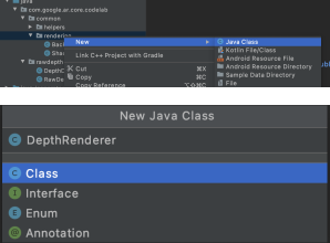
다음으로 Depth API를 호출하여 각 프레임의 깊이 이미지를 가져옵니다. 새 파일을 만들어 깊이 데이터를 새 클래스로 캡슐화합니다. rawdepth 폴더를 마우스 오른쪽 버튼으로 클릭하고 New > Java Class를 선택합니다. 이렇게 하면 빈 파일이 생성됩니다. 이 클래스에 다음을 추가합니다.
src/main/java/com/google/ar/core/codelab/rawdepth/DepthData.java
package com.google.ar.core.codelab.rawdepth;

import android.media.Image;
import android.opengl.Matrix;

import com.google.ar.core.Anchor;
import com.google.ar.core.CameraIntrinsics;
import com.google.ar.core.Frame;
import com.google.ar.core.exceptions.NotYetAvailableException;

import java.nio.ByteBuffer;
import java.nio.ByteOrder;
import java.nio.FloatBuffer;
import java.nio.ShortBuffer;

/**
 * Convert depth data from ARCore depth images to 3D pointclouds. Points are added by calling the
 * Raw Depth API, and reprojected into 3D space.
 */
public class DepthData {
    public static final int FLOATS_PER_POINT = 4; // X,Y,Z,confidence.

}
이 클래스는 깊이 이미지를 포인트 클라우드로 변환하는 데 사용됩니다. 점 클라우드는 각각 3D 좌표 (x, y, z)와 0~1 범위의 신뢰값을 포함하는 점의 목록으로 장면 도형을 나타냅니다.
클래스 하단에 create() 메서드를 추가하여 Raw Depth API로 이러한 값을 채우는 호출을 추가합니다. 이 메서드는 최신 깊이 및 신뢰도 이미지를 쿼리하여 결과 포인트 클라우드를 저장합니다. 깊이 및 신뢰도 이미지에 일치하는 데이터가 포함됩니다.
public static FloatBuffer create(Frame frame, Anchor cameraPoseAnchor) {
    try {
        Image depthImage = frame.acquireRawDepthImage16Bits();
        Image confidenceImage = frame.acquireRawDepthConfidenceImage();

        // Retrieve the intrinsic camera parameters corresponding to the depth image to
        // transform 2D depth pixels into 3D points. See more information about the depth values
        // at
        // https://developers.google.com/ar/develop/java/depth/overview#understand-depth-values.

        final CameraIntrinsics intrinsics = frame.getCamera().getTextureIntrinsics();
        float[] modelMatrix = new float[16];
        cameraPoseAnchor.getPose().toMatrix(modelMatrix, 0);
        final FloatBuffer points = convertRawDepthImagesTo3dPointBuffer(
                depthImage, confidenceImage, intrinsics, modelMatrix);

        depthImage.close();
        confidenceImage.close();

        return points;
    } catch (NotYetAvailableException e) {
        // This normally means that depth data is not available yet.
        // This is normal, so you don't have to spam the logcat with this.
    }
    return null;
}
|
|
|
|
|
|
|
|
이 코드는 이때 카메라 앵커도 저장하므로, 도우미 메서드 convertRawDepthImagesTo3dPointBuffer()를 호출하여 깊이 정보를 세계 좌표로 변환할 수 있습니다. 이 도우미 메서드는 깊이 이미지의 각 픽셀을 가져와 카메라 내장 기능을 사용하여 카메라를 기준으로 한 3D 포인트에 깊이를 투영 해제합니다. 그런 다음 카메라 앵커를 사용하여 점의 위치를 세계 좌표로 변환합니다. 존재하는 각 픽셀은 3D 점 (미터 단위)으로 변환되고 신뢰도와 함께 저장됩니다.
DepthData.java에 다음 도우미 메서드를 추가합니다.
/** Apply camera intrinsics to convert depth image into a 3D pointcloud. */
    private static FloatBuffer convertRawDepthImagesTo3dPointBuffer(
            Image depth, Image confidence, CameraIntrinsics cameraTextureIntrinsics, float[] modelMatrix) {
        // Java uses big endian so change the endianness to ensure
        // that the depth data is in the correct byte order.
        final Image.Plane depthImagePlane = depth.getPlanes()[0];
        ByteBuffer depthByteBufferOriginal = depthImagePlane.getBuffer();
        ByteBuffer depthByteBuffer = ByteBuffer.allocate(depthByteBufferOriginal.capacity());
        depthByteBuffer.order(ByteOrder.LITTLE_ENDIAN);
        while (depthByteBufferOriginal.hasRemaining()) {
            depthByteBuffer.put(depthByteBufferOriginal.get());
        }
        depthByteBuffer.rewind();
        ShortBuffer depthBuffer = depthByteBuffer.asShortBuffer();

        final Image.Plane confidenceImagePlane = confidence.getPlanes()[0];
        ByteBuffer confidenceBufferOriginal = confidenceImagePlane.getBuffer();
        ByteBuffer confidenceBuffer = ByteBuffer.allocate(confidenceBufferOriginal.capacity());
        confidenceBuffer.order(ByteOrder.LITTLE_ENDIAN);
        while (confidenceBufferOriginal.hasRemaining()) {
            confidenceBuffer.put(confidenceBufferOriginal.get());
        }
        confidenceBuffer.rewind();

        // To transform 2D depth pixels into 3D points, retrieve the intrinsic camera parameters
        // corresponding to the depth image. See more information about the depth values at
        // https://developers.google.com/ar/develop/java/depth/overview#understand-depth-values.
        final int[] intrinsicsDimensions = cameraTextureIntrinsics.getImageDimensions();
        final int depthWidth = depth.getWidth();
        final int depthHeight = depth.getHeight();
        final float fx =
                cameraTextureIntrinsics.getFocalLength()[0] * depthWidth / intrinsicsDimensions[0];
        final float fy =
                cameraTextureIntrinsics.getFocalLength()[1] * depthHeight / intrinsicsDimensions[1];
        final float cx =
                cameraTextureIntrinsics.getPrincipalPoint()[0] * depthWidth / intrinsicsDimensions[0];
        final float cy =
                cameraTextureIntrinsics.getPrincipalPoint()[1] * depthHeight / intrinsicsDimensions[1];

        // Allocate the destination point buffer. If the number of depth pixels is larger than
        // `maxNumberOfPointsToRender` we uniformly subsample. The raw depth image may have
        // different resolutions on different devices.
        final float maxNumberOfPointsToRender = 20000;
        int step = (int) Math.ceil(Math.sqrt(depthWidth * depthHeight / maxNumberOfPointsToRender));

        FloatBuffer points = FloatBuffer.allocate(depthWidth / step * depthHeight / step * FLOATS_PER_POINT);
        float[] pointCamera = new float[4];
        float[] pointWorld = new float[4];

        for (int y = 0; y < depthHeight; y += step) {
            for (int x = 0; x < depthWidth; x += step) {
                // Depth images are tightly packed, so it's OK to not use row and pixel strides.
                int depthMillimeters = depthBuffer.get(y * depthWidth + x); // Depth image pixels are in mm.
                if (depthMillimeters == 0) {
                    // Pixels with value zero are invalid, meaning depth estimates are missing from
                    // this location.
                    continue;
                }
                final float depthMeters = depthMillimeters / 1000.0f; // Depth image pixels are in mm.

                // Retrieve the confidence value for this pixel.
                final byte confidencePixelValue =
                        confidenceBuffer.get(
                                y * confidenceImagePlane.getRowStride()
                                        + x * confidenceImagePlane.getPixelStride());
                final float confidenceNormalized = ((float) (confidencePixelValue & 0xff)) / 255.0f;

                // Unproject the depth into a 3D point in camera coordinates.
                pointCamera[0] = depthMeters * (x - cx) / fx;
                pointCamera[1] = depthMeters * (cy - y) / fy;
                pointCamera[2] = -depthMeters;
                pointCamera[3] = 1;

                // Apply model matrix to transform point into world coordinates.
                Matrix.multiplyMV(pointWorld, 0, modelMatrix, 0, pointCamera, 0);
                points.put(pointWorld[0]); // X.
                points.put(pointWorld[1]); // Y.
                points.put(pointWorld[2]); // Z.
                points.put(confidenceNormalized);
            }
        }

        points.rewind();
        return points;
    }
각 프레임의 최신 원시 심도 데이터 가져오기
깊이 정보를 가져오고 각 포즈의 세계 좌표에 정렬하도록 앱을 수정합니다.
RawDepthCodelabActivity.java의 onDrawFrame() 메서드에서 기존 줄을 찾습니다.
Frame frame = session.update();
Camera camera = frame.getCamera();

// If the frame is ready, render the camera preview image to the GL surface.
backgroundRenderer.draw(frame);
바로 아래에 다음 줄을 추가합니다.
// Retrieve the depth data for this frame.
FloatBuffer points = DepthData.create(frame, session.createAnchor(camera.getPose()));
if (points == null) {
  return;
}

if (messageSnackbarHelper.isShowing() && points != null) {
  messageSnackbarHelper.hide(this);
}
6. 깊이 데이터 렌더링 (2부)
이제 깊이 포인트 클라우드를 만들었으므로 데이터가 화면에 렌더링되는 모습을 확인할 차례입니다.
렌더기를 추가하여 깊이 점을 시각화하세요.
렌더기를 추가하여 깊이 점을 시각화합니다.
먼저 렌더링 로직을 포함할 새 클래스를 추가합니다. 이 클래스는 OpenGL 작업을 실행하여 셰이더를 초기화하여 깊이 포인트 클라우드를 시각화합니다.
| DepthRenderer 클래스 추가
|
이 클래스를 다음 코드로 채웁니다.
src/main/java/com/google/ar/core/codelab/common/rendering/DepthRenderer.java
package com.google.ar.core.codelab.common.rendering;

import android.content.Context;
import android.opengl.GLES20;
import android.opengl.Matrix;

import com.google.ar.core.Camera;
import com.google.ar.core.codelab.rawdepth.DepthData;

import java.io.IOException;
import java.nio.FloatBuffer;

public class DepthRenderer {
    private static final String TAG = DepthRenderer.class.getSimpleName();

    // Shader names.
    private static final String VERTEX_SHADER_NAME = "shaders/depth_point_cloud.vert";
    private static final String FRAGMENT_SHADER_NAME = "shaders/depth_point_cloud.frag";

    public static final int BYTES_PER_FLOAT = Float.SIZE / 8;
    private static final int BYTES_PER_POINT = BYTES_PER_FLOAT * DepthData.FLOATS_PER_POINT;
    private static final int INITIAL_BUFFER_POINTS = 1000;

    private int arrayBuffer;
    private int arrayBufferSize;

    private int programName;
    private int positionAttribute;
    private int modelViewProjectionUniform;
    private int pointSizeUniform;

    private int numPoints = 0;

    public DepthRenderer() {}

    public void createOnGlThread(Context context) throws IOException {
        ShaderUtil.checkGLError(TAG, "Bind");

        int[] buffers = new int[1];
        GLES20.glGenBuffers(1, buffers, 0);
        arrayBuffer = buffers[0];
        GLES20.glBindBuffer(GLES20.GL_ARRAY_BUFFER, arrayBuffer);

        arrayBufferSize = INITIAL_BUFFER_POINTS * BYTES_PER_POINT;
        GLES20.glBufferData(GLES20.GL_ARRAY_BUFFER, arrayBufferSize, null, GLES20.GL_DYNAMIC_DRAW);
        GLES20.glBindBuffer(GLES20.GL_ARRAY_BUFFER, 0);

        ShaderUtil.checkGLError(TAG, "Create");

        int vertexShader =
                ShaderUtil.loadGLShader(TAG, context, GLES20.GL_VERTEX_SHADER, VERTEX_SHADER_NAME);
        int fragmentShader =
                ShaderUtil.loadGLShader(TAG, context, GLES20.GL_FRAGMENT_SHADER, FRAGMENT_SHADER_NAME);

        programName = GLES20.glCreateProgram();
        GLES20.glAttachShader(programName, vertexShader);
        GLES20.glAttachShader(programName, fragmentShader);
        GLES20.glLinkProgram(programName);
        GLES20.glUseProgram(programName);

        ShaderUtil.checkGLError(TAG, "Program");

        positionAttribute = GLES20.glGetAttribLocation(programName, "a_Position");
        modelViewProjectionUniform = GLES20.glGetUniformLocation(programName, "u_ModelViewProjection");
        // Sets the point size, in pixels.
        pointSizeUniform = GLES20.glGetUniformLocation(programName, "u_PointSize");

        ShaderUtil.checkGLError(TAG, "Init complete");
    }
}
깊이 데이터 렌더링
다음으로, 렌더링 셰이더의 소스를 제공합니다. DepthRenderer 클래스 하단에 다음 update() 메서드를 추가합니다. 이 메서드는 최신 깊이 정보를 입력으로 가져와 포인트 클라우드 데이터를 GPU에 복사합니다.
    /**
     * Update the OpenGL buffer contents to the provided point. Repeated calls with the same point
     * cloud will be ignored.
     */
    public void update(FloatBuffer points) {
        ShaderUtil.checkGLError(TAG, "Update");
        GLES20.glBindBuffer(GLES20.GL_ARRAY_BUFFER, arrayBuffer);

        // If the array buffer is not large enough to fit the new point cloud, resize it.
        points.rewind();
        numPoints = points.remaining() / DepthData.FLOATS_PER_POINT;
        if (numPoints * BYTES_PER_POINT > arrayBufferSize) {
            while (numPoints * BYTES_PER_POINT > arrayBufferSize) {
                arrayBufferSize *= 2;
            }
            GLES20.glBufferData(GLES20.GL_ARRAY_BUFFER, arrayBufferSize, null, GLES20.GL_DYNAMIC_DRAW);
        }

        GLES20.glBufferSubData(
                GLES20.GL_ARRAY_BUFFER, 0, numPoints * BYTES_PER_POINT, points);
        GLES20.glBindBuffer(GLES20.GL_ARRAY_BUFFER, 0);

        ShaderUtil.checkGLError(TAG, "Update complete");
    }
DepthRenderer 클래스 하단에 draw() 메서드를 추가하여 화면에 최신 데이터를 그립니다. 이 메서드는 3D 점클라우드 정보를 가져와 카메라 뷰로 다시 투영하여 화면에 렌더링할 수 있습니다.
    /** Render the point cloud. The ARCore point cloud is given in world space. */
    public void draw(Camera camera) {
        float[] projectionMatrix = new float[16];
        camera.getProjectionMatrix(projectionMatrix, 0, 0.1f, 100.0f);
        float[] viewMatrix = new float[16];
        camera.getViewMatrix(viewMatrix, 0);
        float[] viewProjection = new float[16];
        Matrix.multiplyMM(viewProjection, 0, projectionMatrix, 0, viewMatrix, 0);

        ShaderUtil.checkGLError(TAG, "Draw");

        GLES20.glUseProgram(programName);
        GLES20.glEnableVertexAttribArray(positionAttribute);
        GLES20.glBindBuffer(GLES20.GL_ARRAY_BUFFER, arrayBuffer);
        GLES20.glVertexAttribPointer(positionAttribute, 4, GLES20.GL_FLOAT, false, BYTES_PER_POINT, 0);
        GLES20.glUniformMatrix4fv(modelViewProjectionUniform, 1, false, viewProjection, 0);
        // Set point size to 5 pixels.
        GLES20.glUniform1f(pointSizeUniform, 5.0f);

        GLES20.glDrawArrays(GLES20.GL_POINTS, 0, numPoints);
        GLES20.glDisableVertexAttribArray(positionAttribute);
        GLES20.glBindBuffer(GLES20.GL_ARRAY_BUFFER, 0);

        ShaderUtil.checkGLError(TAG, "Draw complete");
    }
pointSizeUniform 변수를 사용하여 포인트 크기를 다양한 크기(픽셀 단위)로 설정할 수 있습니다. 샘플 앱에서 pointSizeUniform는 5픽셀로 설정됩니다.
새 셰이더 추가
앱에서 깊이 및 깊이 데이터를 표시하는 방법에는 여러 가지가 있습니다. 여기서는 셰이더 몇 개를 추가하고 간단한 색상 매핑 시각화를 만들어 보겠습니다.
src/main/assets/shaders/ 디렉터리에 새 .vert 및 .frag 셰이더를 추가합니다.
| 새 .vert 셰이더 추가하기Android 스튜디오에서:
|
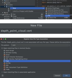
새 .vert 파일에 다음 코드를 추가합니다.
src/main/assets/shaders/depth_point_cloud.vert
uniform mat4 u_ModelViewProjection;
uniform float u_PointSize;

attribute vec4 a_Position;

varying vec4 v_Color;

// Return an interpolated color in a 6 degree polynomial interpolation.
vec3 GetPolynomialColor(in float x,
  in vec4 kRedVec4, in vec4 kGreenVec4, in vec4 kBlueVec4,
  in vec2 kRedVec2, in vec2 kGreenVec2, in vec2 kBlueVec2) {
  // Moves the color space a little bit to avoid pure red.
  // Removes this line for more contrast.
  x = clamp(x * 0.9 + 0.03, 0.0, 1.0);
  vec4 v4 = vec4(1.0, x, x * x, x * x * x);
  vec2 v2 = v4.zw * v4.z;
  return vec3(
    dot(v4, kRedVec4) + dot(v2, kRedVec2),
    dot(v4, kGreenVec4) + dot(v2, kGreenVec2),
    dot(v4, kBlueVec4) + dot(v2, kBlueVec2)
  );
}

// Return a smooth Percept colormap based upon the Turbo colormap.
vec3 PerceptColormap(in float x) {
  const vec4 kRedVec4 = vec4(0.55305649, 3.00913185, -5.46192616, -11.11819092);
  const vec4 kGreenVec4 = vec4(0.16207513, 0.17712472, 15.24091500, -36.50657960);
  const vec4 kBlueVec4 = vec4(-0.05195877, 5.18000081, -30.94853351, 81.96403246);
  const vec2 kRedVec2 = vec2(27.81927491, -14.87899417);
  const vec2 kGreenVec2 = vec2(25.95549545, -5.02738237);
  const vec2 kBlueVec2 = vec2(-86.53476570, 30.23299484);
  const float kInvalidDepthThreshold = 0.01;
  return step(kInvalidDepthThreshold, x) *
         GetPolynomialColor(x, kRedVec4, kGreenVec4, kBlueVec4,
                            kRedVec2, kGreenVec2, kBlueVec2);
}

void main() {
   // Color the pointcloud by height.
   float kMinHeightMeters = -2.0f;
   float kMaxHeightMeters = 2.0f;
   float normalizedHeight = clamp((a_Position.y - kMinHeightMeters) / (kMaxHeightMeters - kMinHeightMeters), 0.0, 1.0);
   v_Color = vec4(PerceptColormap(normalizedHeight), 1.0);
   gl_Position = u_ModelViewProjection * vec4(a_Position.xyz, 1.0);
   gl_PointSize = u_PointSize;
}
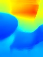
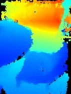
이 셰이더는 개선된 시각화를 위해 Turbo 색상 척도를 사용합니다. 이는 다음 단계를 실행합니다.
- 각 점 (세계 좌표의 y축)의 고도를 검색합니다.
- 해당 고도와 관련된 색상을 계산합니다 (빨간색=낮음, 파란색=높음).
- 각 지점의 화면 위치를 계산합니다.
DepthRenderer.update()메서드에 정의된 대로 각 점의 크기를 픽셀로 설정합니다.
동일한 디렉터리에 프래그먼트 셰이더를 만들고 이름을 depth_point_cloud.frag로 지정하며 이 섹션에서 동일한 단계를 반복합니다.
그런 다음 이 새 파일에 다음 코드를 추가하여 꼭짓점 셰이더에 정의된 대로 각 점을 동일한 색상의 단일 꼭짓점으로 렌더링합니다.
src/main/assets/shaders/depth_point_cloud.frag
precision mediump float;
varying vec4 v_Color;

void main() {
    gl_FragColor = v_Color;
}
이 렌더링을 적용하려면 RawDepthCodelabActivity 내 DepthRenderer 클래스에 호출을 추가합니다.
src/main/java/com/google/ar/core/codelab/common/rendering/RawDepthCodelabActivity.java
import com.google.ar.core.codelab.common.rendering.DepthRenderer;
클래스 상단에서 backgroundRenderer 옆에 비공개 멤버를 추가합니다.
private final DepthRenderer depthRenderer = new DepthRenderer();
depthRenderer는 기존 backgroundRenderer와 마찬가지로 RawDepthCodelabActivity.onSurfaceCreated() 내에서 초기화해야 합니다.
depthRenderer.createOnGlThread(/*context=*/ this);
onDrawFrame 내부의 try-catch 블록 끝에 다음 코드를 추가하여 현재 프레임의 최신 깊이를 표시합니다.
// Visualize depth points.
depthRenderer.update(points);
depthRenderer.draw(camera);
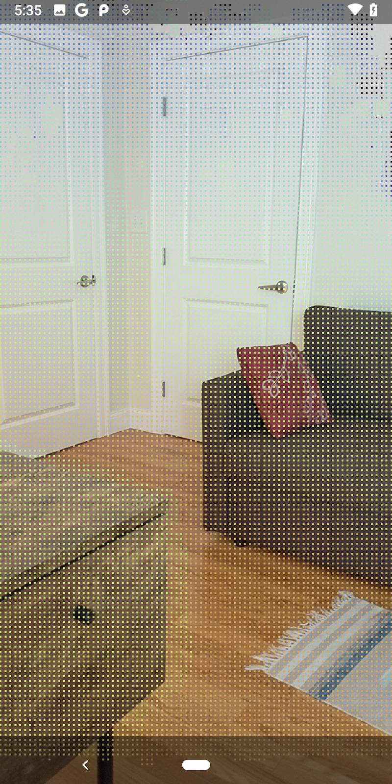
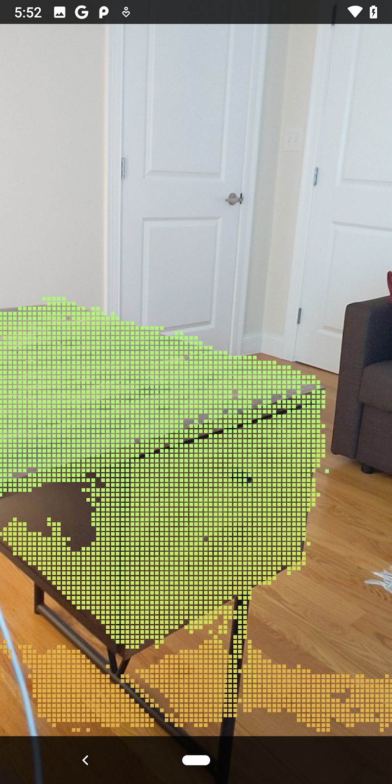
이렇게 변경하면 앱이 성공적으로 빌드되고 깊이 포인트 클라우드가 표시됩니다.
| 원시 깊이 포인트 클라우드 시각화의 예
|
7. 3D 점 구름 분석 (3부)
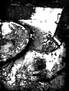
깊이 데이터가 AR 세션에 존재하는지 확인한 후 심도 데이터를 분석할 수 있습니다. 심도를 분석하는 데 중요한 도구는 각 픽셀의 confidence 값입니다. 신뢰도 값을 사용하여 3D 포인트 클라우드를 분석합니다.
신뢰도가 낮은 픽셀 무효화
각 깊이 픽셀의 신뢰도 값을 가져와 DepthData 내부의 각 점과 함께 저장했지만 아직 사용하지 않았습니다.
confidenceNormalized 값의 범위는 0에서 1 사이이며, 0은 신뢰도가 낮음을, 1은 전체 신뢰도를 나타냅니다. 신뢰도가 너무 낮아 유용성이 떨어지는 픽셀이 저장되지 않도록 DepthData 클래스의 convertRawDepthImagesTo3dPointBuffer() 메서드를 수정합니다.
final float confidenceNormalized = ((float) (confidencePixelValue & 0xff)) / 255.0f;

// ******** New code to add ************
if (confidenceNormalized < 0.3) {
   // Ignores "low-confidence" pixels.
   continue;
}
// ******** End of new code to add *********
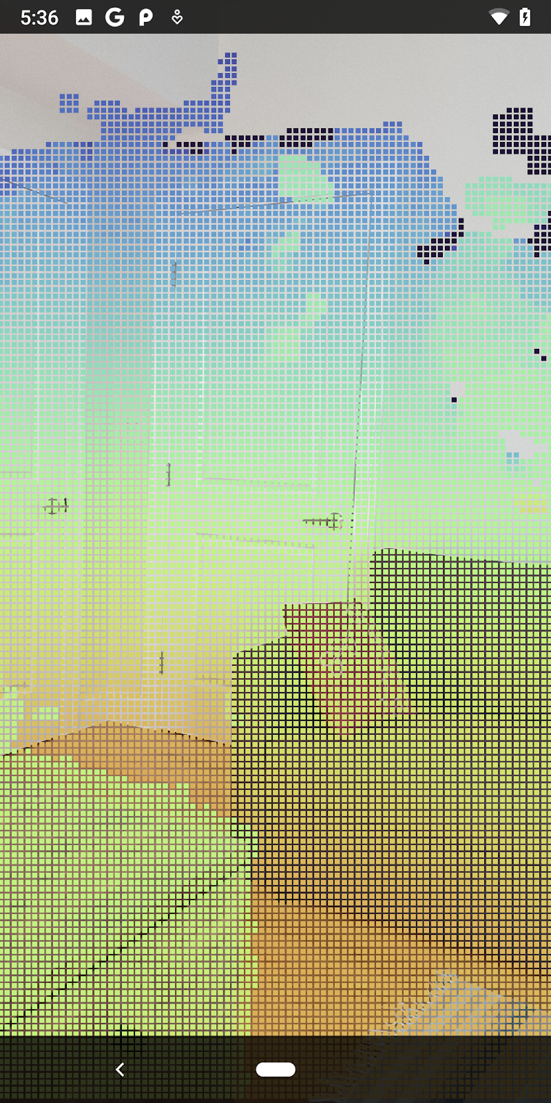
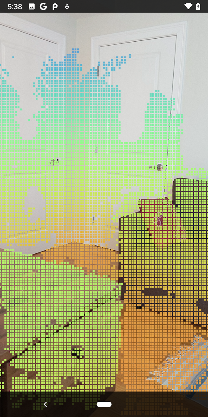
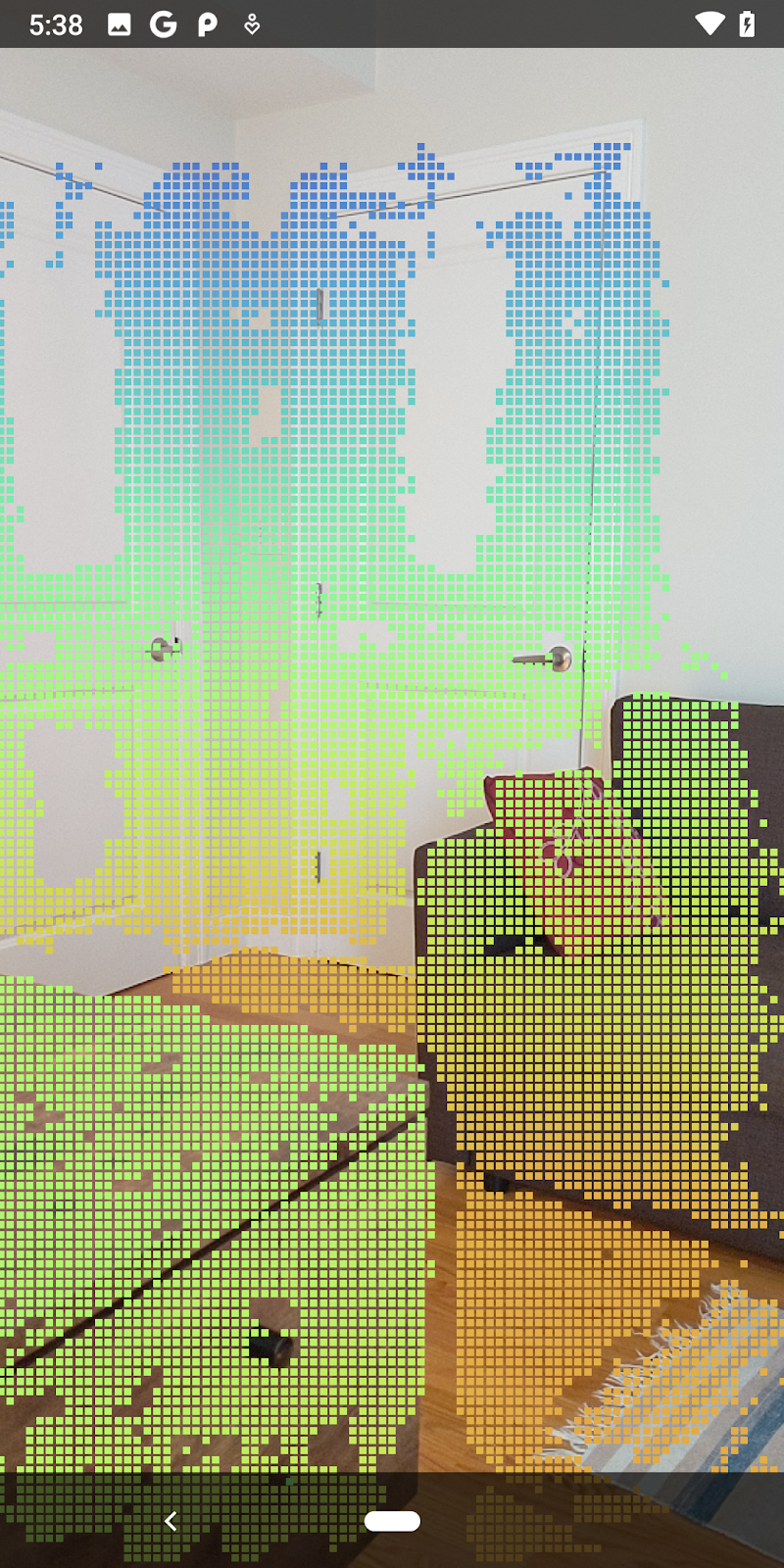
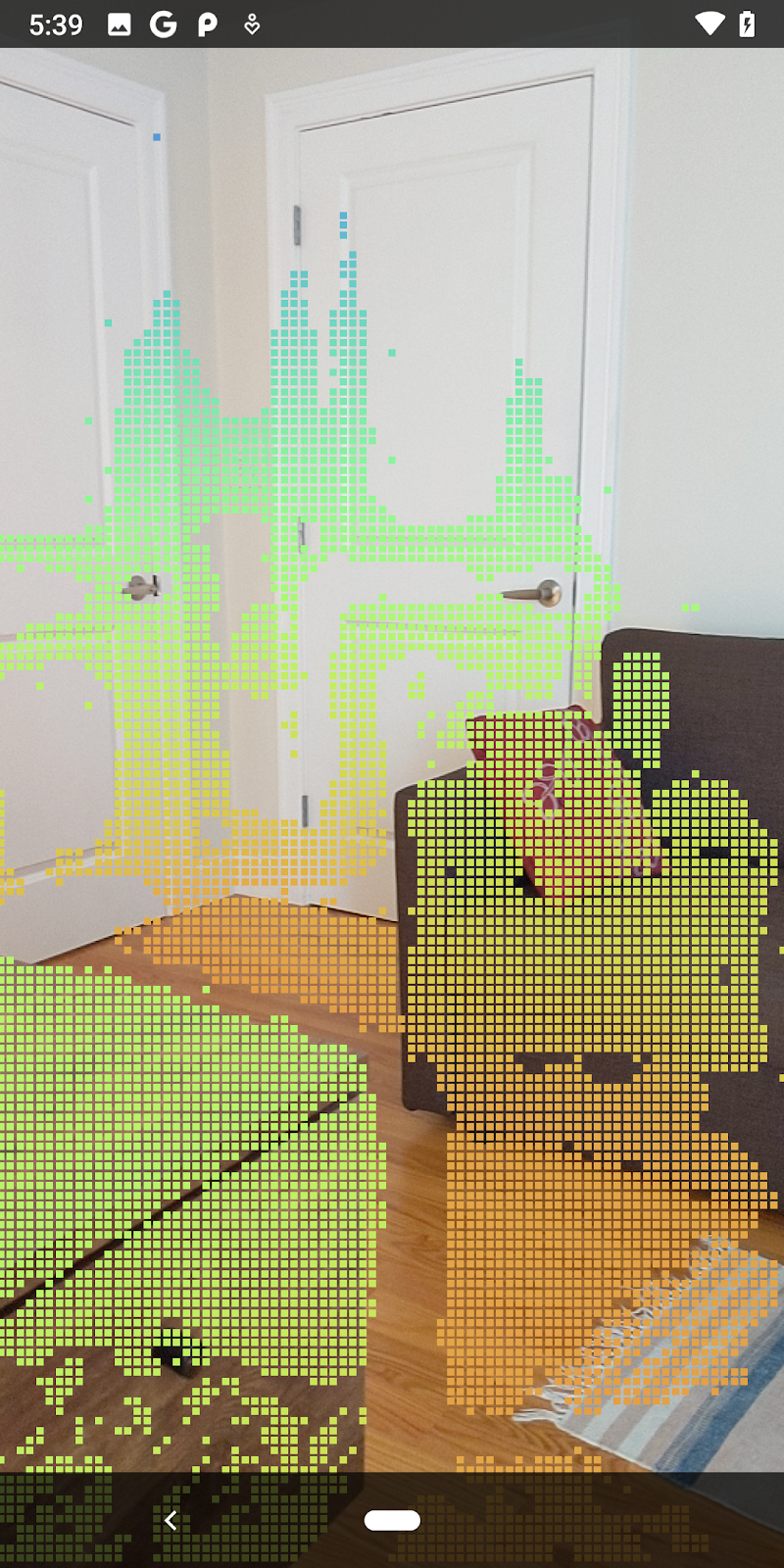
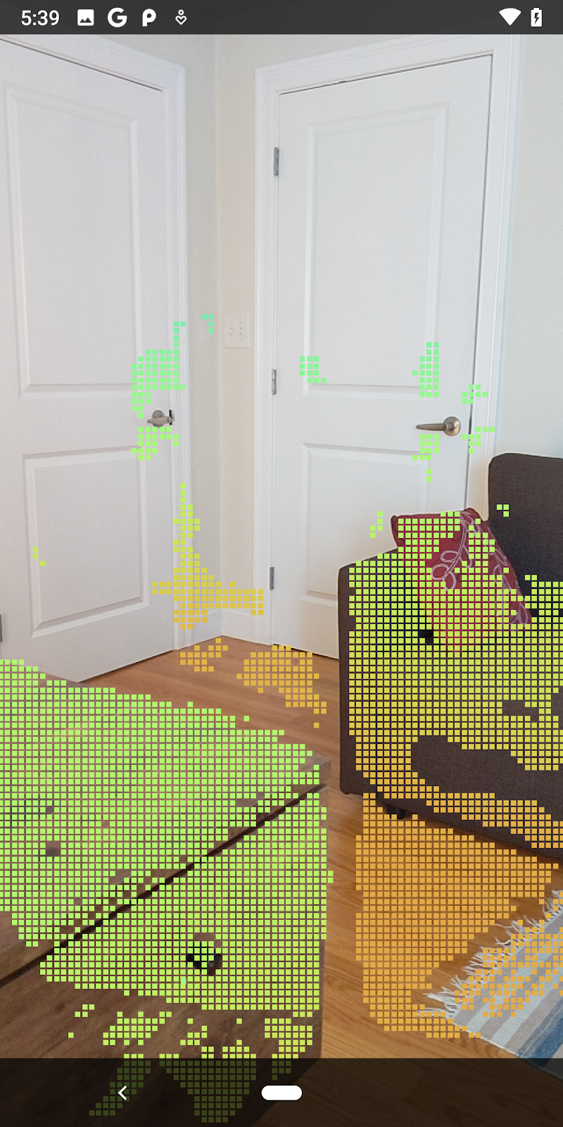
신뢰도 수준에 다양한 임곗값을 시도하여 각 수준에서 얼마나 많은 심도 포인트가 유지되는지 확인하세요.
|
|
|
|
|
신뢰도 >= 0.1 | 신뢰도 >= 0.3 | 신뢰도 >= 0.5 | 신뢰도 >= 0.7 | 신뢰도 0.9 이상 |

거리로 픽셀 필터링
거리별로 심도 픽셀을 필터링할 수도 있습니다. 다음 단계에서는 카메라에 가까운 도형을 다룹니다. 성능 최적화를 위해 너무 멀리 있는 지점은 무시해도 됩니다.
방금 추가한 신뢰도 확인 코드를 다음을 사용하여 업데이트합니다.
src/main/java/com/google/ar/core/codelab/rawdepth/DepthData.java
if (confidenceNormalized < 0.3 || depthMeters > 1.5) {
    // Ignore "low-confidence" pixels or depth that is too far away.
   continue;
 }
신뢰도가 높은 점과 종료점만 표시됩니다.
| 거리 필터링포인트 클라우드가 카메라에서 1.5미터 이내에 있도록 제한합니다. |
3D 점과 평면 비교
도형의 3D 점과 평면을 비교하고 관측된 AR 평면에 가까운 점을 삭제하는 등 서로 필터링할 수 있습니다.
이 단계에서는 '비평면'만 남깁니다. 점의 경계선에 위치합니다. DepthData 클래스 하단에 filterUsingPlanes() 메서드를 추가합니다. 이 메서드는 기존 점을 반복하고 각 평면에 대해 각 점을 확인하고 AR 평면에 너무 가까운 지점을 무효화하여 장면에서 객체를 강조 표시하는 평면이 아닌 영역을 남겨둡니다.
src/main/java/com/google/ar/core/codelab/rawdepth/DepthData.java
    public static void filterUsingPlanes(FloatBuffer points, Collection<Plane> allPlanes) {
        float[] planeNormal = new float[3];

        // Allocate the output buffer.
        int numPoints = points.remaining() / DepthData.FLOATS_PER_POINT;

        // Check each plane against each point.
        for (Plane plane : allPlanes) {
            if (plane.getTrackingState() != TrackingState.TRACKING || plane.getSubsumedBy() != null) {
                continue;
            }

            // Compute the normal vector of the plane.
            Pose planePose = plane.getCenterPose();
            planePose.getTransformedAxis(1, 1.0f, planeNormal, 0);

            // Filter points that are too close to the plane.
            for (int index = 0; index < numPoints; ++index) {
                // Retrieves the next point.
                final float x = points.get(FLOATS_PER_POINT * index);
                final float y = points.get(FLOATS_PER_POINT * index + 1);
                final float z = points.get(FLOATS_PER_POINT * index + 2);

                // Transform point to be in world coordinates, to match plane info.
                float distance = (x - planePose.tx()) * planeNormal[0]
                        + (y - planePose.ty()) * planeNormal[1]
                        + (z - planePose.tz()) * planeNormal[2];
                // Controls the size of objects detected.
                // Smaller values mean smaller objects will be kept.
                // Larger values will only allow detection of larger objects, but also helps reduce noise.
                if (Math.abs(distance) > 0.03) {
                    continue;  // Keep this point, since it's far enough away from the plane.
                }

                // Invalidate points that are too close to planar surfaces.
                points.put(FLOATS_PER_POINT * index, 0);
                points.put(FLOATS_PER_POINT * index + 1, 0);
                points.put(FLOATS_PER_POINT * index + 2, 0);
                points.put(FLOATS_PER_POINT * index + 3, 0);
            }
        }
    }
이 메서드를 onDrawFrame 메서드의 RawDepthCodelabActivity에 추가할 수 있습니다.
//  ********** New code to add ************
  // Filter the depth data.
  DepthData.filterUsingPlanes(points, session.getAllTrackables(Plane.class));
//  ********** End new code to add *******

  // Visualize depth points.
  depthRenderer.update(points);
  depthRenderer.draw(camera);
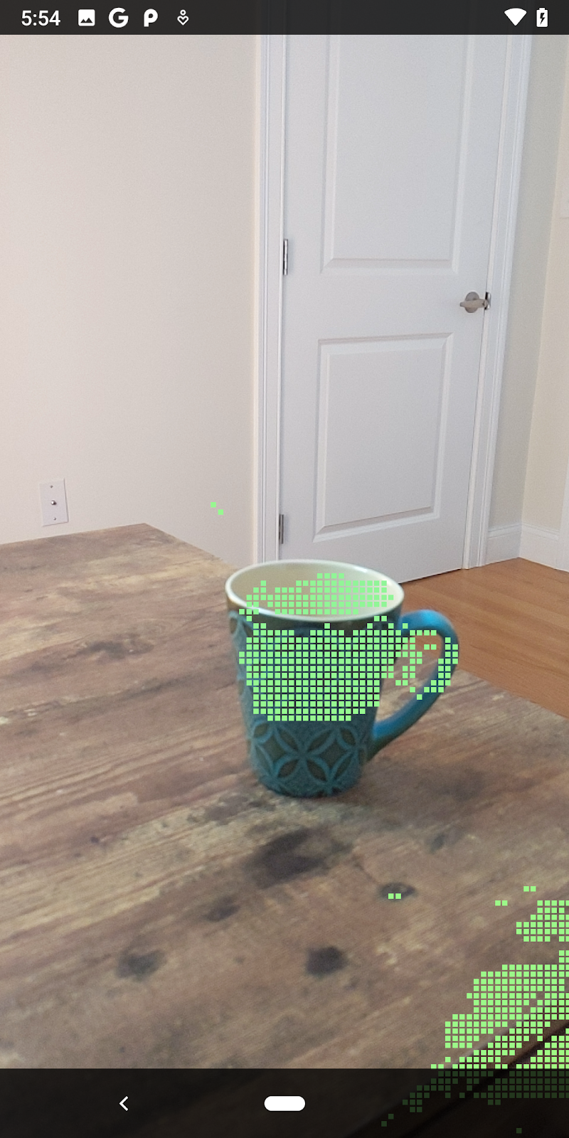
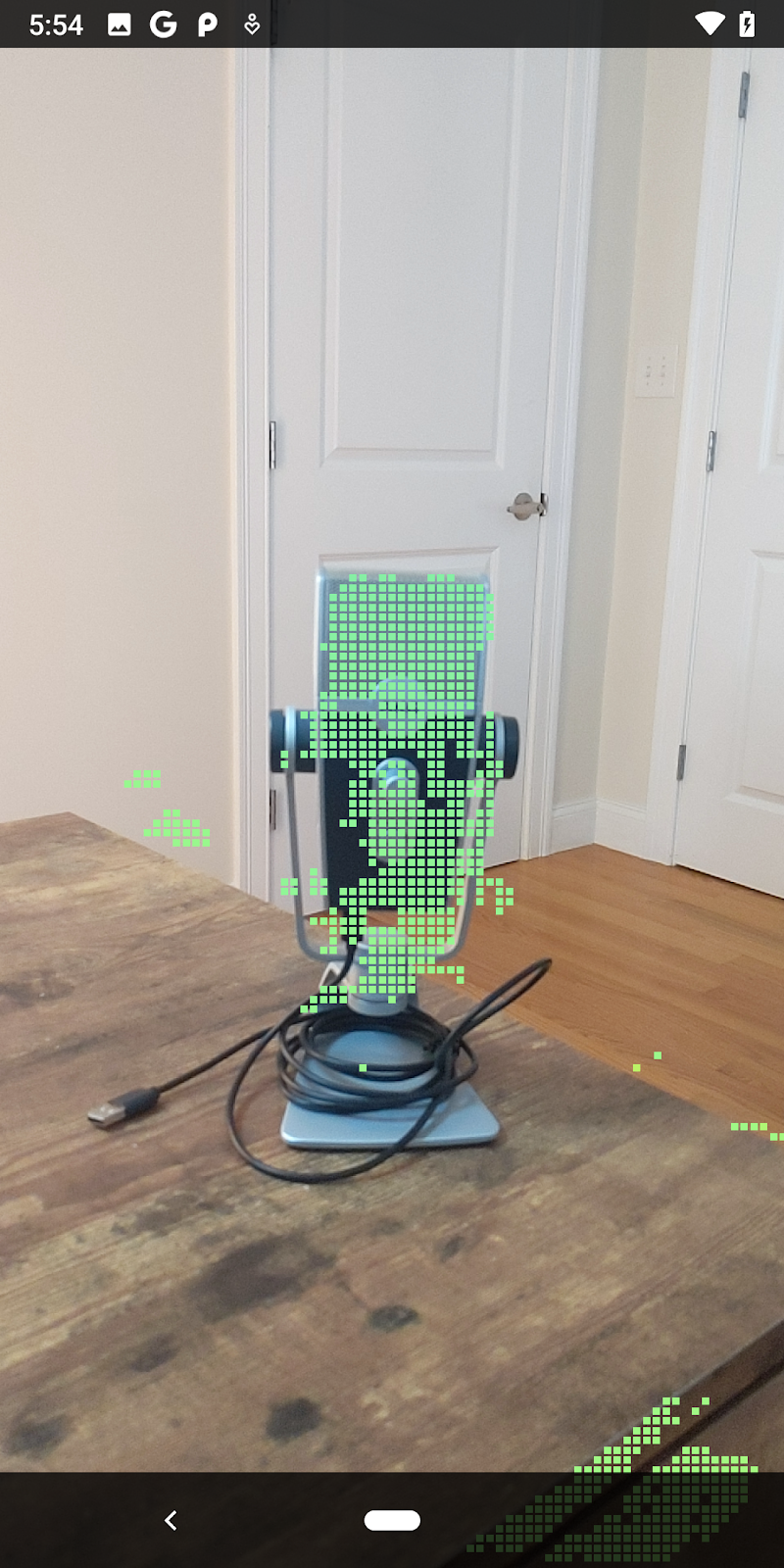
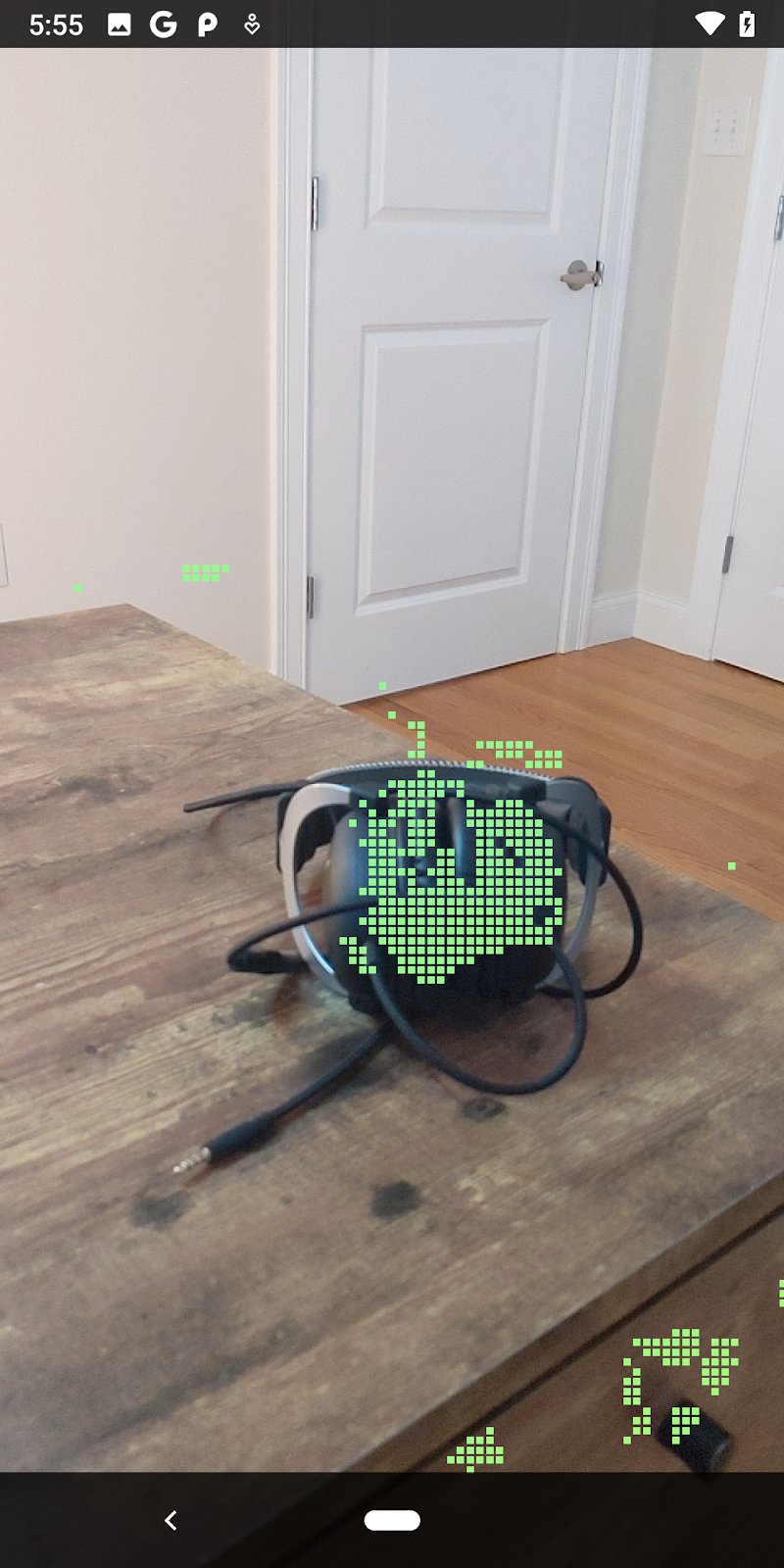
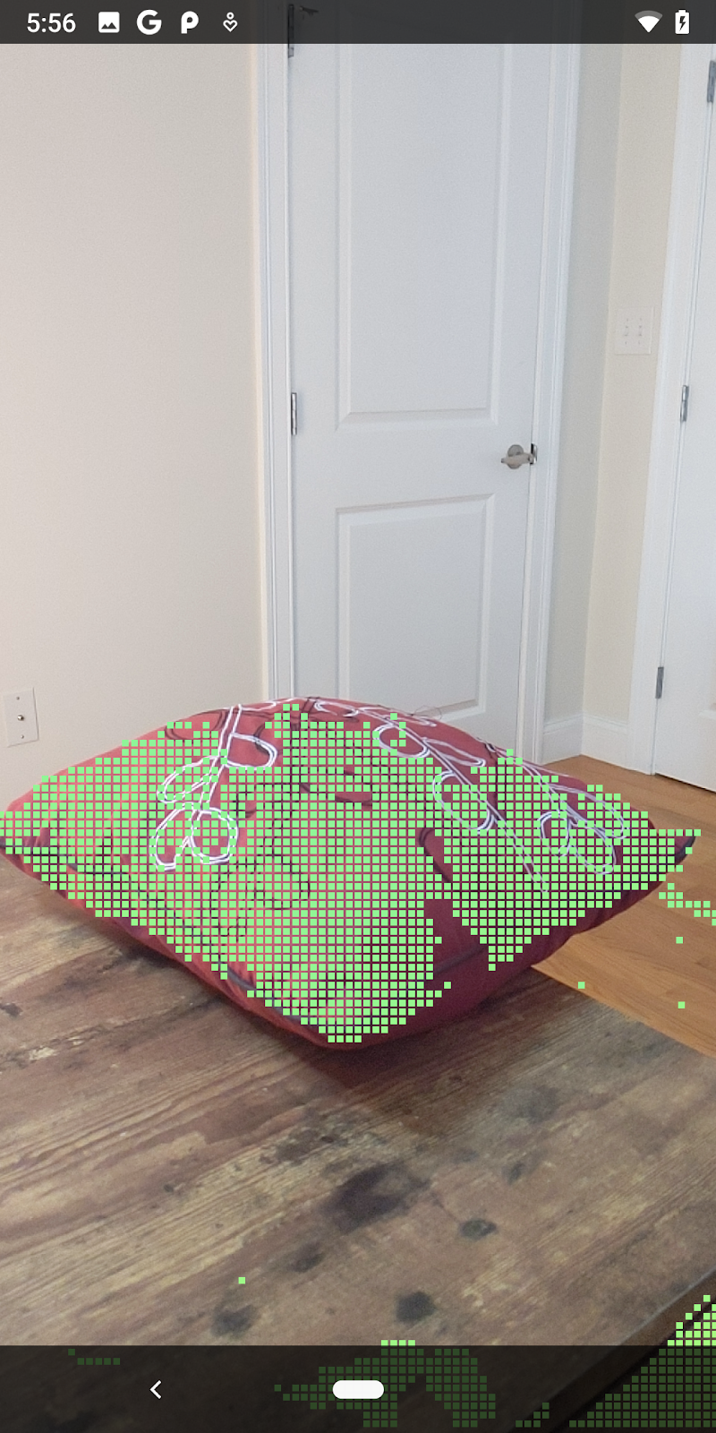
이제 Codelab을 실행하면 점의 하위 집합이 렌더링됩니다. 이러한 점들은 장면에 있는 객체를 나타내며, 객체가 있는 평평한 표면은 무시합니다. 이러한 데이터를 사용하여 점을 함께 클러스터링하여 객체의 크기와 위치를 추정할 수 있습니다.
|
|
|
|
차 한 잔 | 마이크 | 헤드폰 | Pillow |
클러스터 포인트
이 Codelab에는 매우 단순한 포인트 클라우드 클러스터링 알고리즘이 포함되어 있습니다. 검색된 포인트 클라우드를 축 정렬 경계 상자로 정의된 클러스터로 그룹화하도록 Codelab을 업데이트합니다.
src/main/java/com/google/ar/core/codelab/rawdepth/RawDepthCodelabActivity.java
import com.google.ar.core.codelab.common.helpers.AABB;
import com.google.ar.core.codelab.common.helpers.PointClusteringHelper;
import com.google.ar.core.codelab.common.rendering.BoxRenderer;
import java.util.List;
파일 상단에 있는 이 클래스에 다른 렌더기와 함께 BoxRenderer를 추가합니다.
private final BoxRenderer boxRenderer = new BoxRenderer();
onSurfaceCreated() 메서드 내에서 다음을 다른 렌더기와 함께 추가합니다.
boxRenderer.createOnGlThread(/*context=*/this);
마지막으로 RawDepthCodelabActivity 내 onDrawFrame()에 다음 줄을 추가하여 검색된 포인트 클라우드를 클러스터로 그룹화하고 결과를 축 정렬 경계 상자로 렌더링합니다.
      // Visualize depth points.
      depthRenderer.update(points);
      depthRenderer.draw(camera);

// ************ New code to add ***************

      // Draw boxes around clusters of points.
      PointClusteringHelper clusteringHelper = new PointClusteringHelper(points);
      List<AABB> clusters = clusteringHelper.findClusters();
      for (AABB aabb : clusters) {
        boxRenderer.draw(aabb, camera);
      }

// ************ End new code to add ***************
|
|
|
|
차 한 잔 | 마이크 | 헤드폰 | Pillow |
이제 ARCore 세션을 통해 원시 깊이를 가져오고, 깊이 정보를 3D 포인트클라우드로 변환하고, 해당 지점에서 기본 필터링 및 렌더링 작업을 수행할 수 있습니다.
8. 빌드, 실행, 테스트
앱을 빌드, 실행, 테스트합니다.
앱 빌드 및 실행
앱을 빌드하고 실행하려면 다음 단계를 따르세요.
- USB를 통해 ARCore 지원 기기를 연결합니다.
- 메뉴 바에서 ► 버튼을 사용하여 프로젝트를 실행하세요.
- 앱이 빌드되고 기기에 배포될 때까지 기다립니다.
기기에 앱을 처음 배포하려고 하면 다음 단계를 따라야 합니다.
USB 디버깅 허용
메시지가 표시됩니다. 계속하려면 OK를 선택합니다.
기기에서 앱을 처음 실행하면 앱에 기기 카메라 사용 권한이 있는지 묻는 메시지가 표시됩니다. AR 기능을 계속 사용하려면 액세스를 허용해야 합니다.
앱 테스트하기
앱을 실행할 때 기기를 들고 공간을 돌아다니며 천천히 영역을 스캔하여 기본 동작을 테스트할 수 있습니다. 최소 10초 이상 데이터를 수집하고 여러 방향에서 영역을 스캔한 후에 다음 단계로 진행합니다.
9. 축하합니다
축하합니다. Google의 ARCore Raw Depth API를 사용하여 첫 번째 깊이 기반 증강 현실 앱을 빌드하고 실행했습니다. 여러분이 무엇을 빌드할지 정말 기대됩니다.
10. 문제 해결
Android 기기를 개발용으로 설정
- USB 케이블을 사용하여 기기를 개발 머신에 연결합니다. Windows를 사용하여 개발하는 경우 기기에 맞는 USB 드라이버를 설치해야 할 수도 있습니다.
- 다음 단계를 실행하여 개발자 옵션 창에서 USB 디버깅을 사용 설정합니다.
- 설정 앱을 엽니다.
- 기기에서 Android v8.0 이상을 사용한다면 System을 선택합니다.
- 아래로 스크롤하여 휴대전화 정보를 선택합니다.
- 하단으로 스크롤하여 빌드 번호를 7번 탭합니다.
- 이전 화면으로 돌아가서 하단으로 스크롤한 다음 개발자 옵션을 탭합니다.
- 개발자 옵션 창에서 하단으로 스크롤하여 USB 디버깅을 찾아 사용 설정합니다.
이 프로세스에 관한 세부정보는 Google의 Android 개발자 웹사이트를 참고하세요.
라이선스 관련 빌드 실패
라이선스 (Failed to install the following Android SDK packages as some licences have not been accepted)와 관련된 빌드 실패가 발생하면 다음 명령어를 사용하여 이러한 라이선스를 검토하고 수락할 수 있습니다.
cd <path to Android SDK>
tools/bin/sdkmanager --licenses