
1. はじめに
ARCore は、モバイル デバイスで拡張現実(AR)アプリを作成するためのプラットフォームです。Google の ARCore Depth API を使うと、ARCore セッションの各フレームの深度画像にアクセスできます。深度画像の各ピクセルは、カメラから環境までの距離の測定値を表します。
Raw Depth API は、結果を平滑化して補間するように設計されたスクリーンスペース フィルタリング オペレーションを通過していない深度画像を提供します。これらの値は幾何学的にはより正確ですが、欠損データが含まれている可能性があり、関連するカメラ画像との整合性が低い可能性があります。
この Codelab では、Raw Depth API を使用してシーンの 3D ジオメトリ分析を行う方法を紹介します。この Codelab では、未加工の深度データを使用して世界のジオメトリを検出して可視化する、シンプルな AR 対応アプリを作成します。
Depth API と Raw Depth API は、ARCore 対応デバイスの一部でのみサポートされます。Depth API を利用できるのは Android だけです。
作成するアプリの概要
この Codelab では、各フレームの未加工の深度画像を使用して周囲の世界の幾何学的分析を行うアプリを作成します。このアプリは次のことを行います。
- ターゲット デバイスが Depth に対応しているかどうかを確認します。
- 各カメラフレームの未加工の深度画像を取得します。
- 未加工の深度画像を 3D ポイントに再投影し、信頼度とジオメトリに基づいてそれらのポイントをフィルタします。
- 生の深度ポイント クラウドを使用して、対象の 3D オブジェクトをセグメント化します。
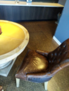
|
作成する内容のプレビュー。 |
注: 途中で問題が発生した場合は、最後のセクションに移動して、トラブルシューティングのヒントを確認してください。
2. 前提条件
この Codelab を完了するには、特定のハードウェアとソフトウェアが必要になります。
ハードウェア要件
- USB デバッグが有効で、USB ケーブル経由で開発マシンに接続された ARCore 対応デバイス。このデバイスは Depth API にも対応している必要があります。
ソフトウェアの要件
- ARCore SDK 1.31.0 以降。
- Android Studio(v4.0.1 以降)がインストールされた開発マシン。
3. セットアップ
開発マシンをセットアップする
ARCore デバイスを USB ケーブルでパソコンに接続します。開発用デバイスでは USB デバッグを許可してください。ターミナルを開いて、次のように adb devices を実行します。
adb devices

List of devices attached
<DEVICE_SERIAL_NUMBER>    device
<DEVICE_SERIAL_NUMBER> は開発用デバイスに固有の文字列です。デバイスが 1 台だけ表示されていることを確認してから、次へ進んでください。
コードをダウンロードしてインストールする
次のようにしてリポジトリのクローンを作成できます。
git clone https://github.com/googlecodelabs/arcore-rawdepthapi
または、次のボタンで ZIP ファイルをダウンロードして展開します。
コードの操作を開始する手順は次のとおりです。
- Android Studio を起動し、[Open an existing Android Studio project] を選択します。
- Raw Depth ZIP ファイルを保存したローカル ディレクトリに移動します。
arcore_rawdepthapi_codelabディレクトリをダブルクリックします。
arcore_rawdepthapi_codelab ディレクトリは、複数のモジュールがある単一の Gradle プロジェクトです。Android Studio の左上に [Project] ペインがまだ表示されていない場合は、プルダウン メニューから [Projects] をクリックします。
結果は次のようになります。
| このプロジェクトに含まれるモジュール:
|
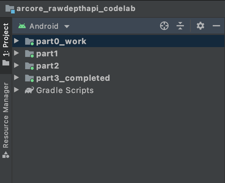
part0_work モジュールで作業します。また、Codelab の各パートに完全な解答が用意されています。各モジュールはビルド可能なアプリになっています。
4. スターター アプリを実行する
Raw Depth スターター アプリを実行する手順は次のとおりです。
- [Run] > [Run...] > [‘part0_work'] をクリックします。
- [Select Deployment Target] ダイアログで、[Connected Devices] リストからデバイスを選択し、[OK] をクリックします。
Android Studio によって初期アプリがビルドされ、開発用デバイスで実行されます。
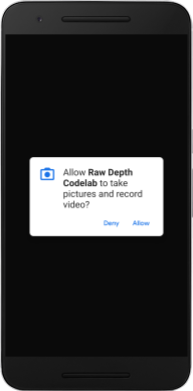
| 初めてアプリを実行したとき、CAMERA パーミッションがリクエストされます。[許可] をタップして続行します。 |
| 現在、このアプリは何も行いません。これは最も基本的な AR アプリケーションで、シーンのカメラビューを表示しますが、それ以外のことは何も行いません。既存のコードは、ARCore SDK とともに公開されている Hello AR サンプルに類似しています。 |
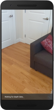
次に、Raw Depth API を使用して、周囲のシーンのジオメトリを取得します。
5. Raw Depth API を設定する(パート 1)
対象デバイスが深度をサポートしていることを確認する
すべての ARCore 対応デバイスで Depth API を実行できるわけではありません。新しいセッションが作成される RawDepthCodelabActivity.java の onResume() 関数内でアプリに機能を追加する前に、ターゲット デバイスが Depth をサポートしていることを確認します。
次の既存のコードを見つけます。
// Create the ARCore session.
session = new Session(/* context= */ this);
更新して、Depth API をサポートできるデバイスでのみアプリケーションが実行されるようにします。
// Create the ARCore session.
session = new Session(/* context= */ this);
if (!session.isDepthModeSupported(Config.DepthMode.RAW_DEPTH_ONLY)) {
  message =
     "This device does not support the ARCore Raw Depth API. See" +
     "https://developers.google.com/ar/devices for
     a list of devices that do.";
}
Raw Depth を有効にする
Raw Depth API は、平滑化されていない深度画像と、対応する信頼度画像を提供します。この信頼度画像には、Raw 深度画像の各ピクセルの深度信頼度が含まれています。先ほど変更した try-catch ステートメントの下にある次のコードを更新して、Raw Depth を有効にします。
try {
  // ************ New code to add ***************
  // Enable raw depth estimation and auto focus mode while ARCore is running.
  Config config = session.getConfig();
  config.setDepthMode(Config.DepthMode.RAW_DEPTH_ONLY);
  config.setFocusMode(Config.FocusMode.AUTO);
  session.configure(config);
  // ************ End new code to add ***************
  session.resume();
} catch (CameraNotAvailableException e) {
  messageSnackbarHelper.showError(this, "Camera not available. Try restarting the app.");
  session = null;
  return;
}
これで AR セッションが適切に構成され、アプリで深度ベースの機能を使用できるようになります。
Depth API を呼び出す
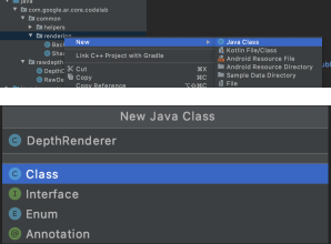
次に、Depth API を呼び出してフレームごとに深度画像を取得します。新しいファイルを作成して、深度データを新しいクラスにカプセル化します。rawdepth フォルダを右クリックして、New > Java Class を選択します。これにより、空のファイルが作成されます。このクラスに以下を追加します。
src/main/java/com/google/ar/core/codelab/rawdepth/DepthData.java
package com.google.ar.core.codelab.rawdepth;

import android.media.Image;
import android.opengl.Matrix;

import com.google.ar.core.Anchor;
import com.google.ar.core.CameraIntrinsics;
import com.google.ar.core.Frame;
import com.google.ar.core.exceptions.NotYetAvailableException;

import java.nio.ByteBuffer;
import java.nio.ByteOrder;
import java.nio.FloatBuffer;
import java.nio.ShortBuffer;

/**
 * Convert depth data from ARCore depth images to 3D pointclouds. Points are added by calling the
 * Raw Depth API, and reprojected into 3D space.
 */
public class DepthData {
    public static final int FLOATS_PER_POINT = 4; // X,Y,Z,confidence.

}
このクラスは、深度画像をポイント クラウドに変換するために使用されます。ポイント クラウドは、3D 座標(x、y、z)と 0 ~ 1 の範囲の信頼度値を持つポイントのリストでシーンのジオメトリを表します。
クラスの末尾に create() メソッドを追加して、Raw Depth API を使用してこれらの値を入力する呼び出しを追加します。このメソッドは、最新の深度画像と信頼度画像をクエリし、結果のポイント クラウドを保存します。深度画像と信頼度画像には一致するデータが含まれます。
public static FloatBuffer create(Frame frame, Anchor cameraPoseAnchor) {
    try {
        Image depthImage = frame.acquireRawDepthImage16Bits();
        Image confidenceImage = frame.acquireRawDepthConfidenceImage();

        // Retrieve the intrinsic camera parameters corresponding to the depth image to
        // transform 2D depth pixels into 3D points. See more information about the depth values
        // at
        // https://developers.google.com/ar/develop/java/depth/overview#understand-depth-values.

        final CameraIntrinsics intrinsics = frame.getCamera().getTextureIntrinsics();
        float[] modelMatrix = new float[16];
        cameraPoseAnchor.getPose().toMatrix(modelMatrix, 0);
        final FloatBuffer points = convertRawDepthImagesTo3dPointBuffer(
                depthImage, confidenceImage, intrinsics, modelMatrix);

        depthImage.close();
        confidenceImage.close();

        return points;
    } catch (NotYetAvailableException e) {
        // This normally means that depth data is not available yet.
        // This is normal, so you don't have to spam the logcat with this.
    }
    return null;
}
|
|
|
|
|
|
|
|
このとき、カメラ アンカーも保存されるため、ヘルパー メソッド convertRawDepthImagesTo3dPointBuffer() を呼び出すことで、深度情報をワールド座標に変換できます。このヘルパー メソッドは、深度画像の各ピクセルを取得し、カメラの内部パラメータを使用して深度をカメラを基準とした 3D ポイントに逆投影します。次に、カメラ アンカーを使用して、ポイントの位置を世界座標に変換します。存在する各ピクセルは 3D ポイント(メートル単位)に変換され、信頼度とともに保存されます。
DepthData.java に次のヘルパー メソッドを追加します。
/** Apply camera intrinsics to convert depth image into a 3D pointcloud. */
    private static FloatBuffer convertRawDepthImagesTo3dPointBuffer(
            Image depth, Image confidence, CameraIntrinsics cameraTextureIntrinsics, float[] modelMatrix) {
        // Java uses big endian so change the endianness to ensure
        // that the depth data is in the correct byte order.
        final Image.Plane depthImagePlane = depth.getPlanes()[0];
        ByteBuffer depthByteBufferOriginal = depthImagePlane.getBuffer();
        ByteBuffer depthByteBuffer = ByteBuffer.allocate(depthByteBufferOriginal.capacity());
        depthByteBuffer.order(ByteOrder.LITTLE_ENDIAN);
        while (depthByteBufferOriginal.hasRemaining()) {
            depthByteBuffer.put(depthByteBufferOriginal.get());
        }
        depthByteBuffer.rewind();
        ShortBuffer depthBuffer = depthByteBuffer.asShortBuffer();

        final Image.Plane confidenceImagePlane = confidence.getPlanes()[0];
        ByteBuffer confidenceBufferOriginal = confidenceImagePlane.getBuffer();
        ByteBuffer confidenceBuffer = ByteBuffer.allocate(confidenceBufferOriginal.capacity());
        confidenceBuffer.order(ByteOrder.LITTLE_ENDIAN);
        while (confidenceBufferOriginal.hasRemaining()) {
            confidenceBuffer.put(confidenceBufferOriginal.get());
        }
        confidenceBuffer.rewind();

        // To transform 2D depth pixels into 3D points, retrieve the intrinsic camera parameters
        // corresponding to the depth image. See more information about the depth values at
        // https://developers.google.com/ar/develop/java/depth/overview#understand-depth-values.
        final int[] intrinsicsDimensions = cameraTextureIntrinsics.getImageDimensions();
        final int depthWidth = depth.getWidth();
        final int depthHeight = depth.getHeight();
        final float fx =
                cameraTextureIntrinsics.getFocalLength()[0] * depthWidth / intrinsicsDimensions[0];
        final float fy =
                cameraTextureIntrinsics.getFocalLength()[1] * depthHeight / intrinsicsDimensions[1];
        final float cx =
                cameraTextureIntrinsics.getPrincipalPoint()[0] * depthWidth / intrinsicsDimensions[0];
        final float cy =
                cameraTextureIntrinsics.getPrincipalPoint()[1] * depthHeight / intrinsicsDimensions[1];

        // Allocate the destination point buffer. If the number of depth pixels is larger than
        // `maxNumberOfPointsToRender` we uniformly subsample. The raw depth image may have
        // different resolutions on different devices.
        final float maxNumberOfPointsToRender = 20000;
        int step = (int) Math.ceil(Math.sqrt(depthWidth * depthHeight / maxNumberOfPointsToRender));

        FloatBuffer points = FloatBuffer.allocate(depthWidth / step * depthHeight / step * FLOATS_PER_POINT);
        float[] pointCamera = new float[4];
        float[] pointWorld = new float[4];

        for (int y = 0; y < depthHeight; y += step) {
            for (int x = 0; x < depthWidth; x += step) {
                // Depth images are tightly packed, so it's OK to not use row and pixel strides.
                int depthMillimeters = depthBuffer.get(y * depthWidth + x); // Depth image pixels are in mm.
                if (depthMillimeters == 0) {
                    // Pixels with value zero are invalid, meaning depth estimates are missing from
                    // this location.
                    continue;
                }
                final float depthMeters = depthMillimeters / 1000.0f; // Depth image pixels are in mm.

                // Retrieve the confidence value for this pixel.
                final byte confidencePixelValue =
                        confidenceBuffer.get(
                                y * confidenceImagePlane.getRowStride()
                                        + x * confidenceImagePlane.getPixelStride());
                final float confidenceNormalized = ((float) (confidencePixelValue & 0xff)) / 255.0f;

                // Unproject the depth into a 3D point in camera coordinates.
                pointCamera[0] = depthMeters * (x - cx) / fx;
                pointCamera[1] = depthMeters * (cy - y) / fy;
                pointCamera[2] = -depthMeters;
                pointCamera[3] = 1;

                // Apply model matrix to transform point into world coordinates.
                Matrix.multiplyMV(pointWorld, 0, modelMatrix, 0, pointCamera, 0);
                points.put(pointWorld[0]); // X.
                points.put(pointWorld[1]); // Y.
                points.put(pointWorld[2]); // Z.
                points.put(confidenceNormalized);
            }
        }

        points.rewind();
        return points;
    }
各フレームの最新の Raw Depth データを取得する
アプリを変更して、深度情報を取得し、各ポーズのワールド座標に合わせます。
RawDepthCodelabActivity.java の onDrawFrame() メソッドで、次の既存の行を見つけます。
Frame frame = session.update();
Camera camera = frame.getCamera();

// If the frame is ready, render the camera preview image to the GL surface.
backgroundRenderer.draw(frame);
そのすぐ下に次の行を追加します。
// Retrieve the depth data for this frame.
FloatBuffer points = DepthData.create(frame, session.createAnchor(camera.getPose()));
if (points == null) {
  return;
}

if (messageSnackbarHelper.isShowing() && points != null) {
  messageSnackbarHelper.hide(this);
}
6. 深度データをレンダリングする(パート 2)
深度ポイント クラウドが用意できたので、画面にレンダリングされたデータがどのように見えるかを確認します。
レンダラを追加して深度ポイントを可視化する
デプスポイントを可視化するレンダラを追加します。
まず、レンダリング ロジックを含む新しいクラスを追加します。このクラスは、深度ポイント クラウドを可視化するためにシェーダーを初期化する OpenGL オペレーションを実行します。
| DepthRenderer クラスを追加
|
このクラスに次のコードを入力します。
src/main/java/com/google/ar/core/codelab/common/rendering/DepthRenderer.java
package com.google.ar.core.codelab.common.rendering;

import android.content.Context;
import android.opengl.GLES20;
import android.opengl.Matrix;

import com.google.ar.core.Camera;
import com.google.ar.core.codelab.rawdepth.DepthData;

import java.io.IOException;
import java.nio.FloatBuffer;

public class DepthRenderer {
    private static final String TAG = DepthRenderer.class.getSimpleName();

    // Shader names.
    private static final String VERTEX_SHADER_NAME = "shaders/depth_point_cloud.vert";
    private static final String FRAGMENT_SHADER_NAME = "shaders/depth_point_cloud.frag";

    public static final int BYTES_PER_FLOAT = Float.SIZE / 8;
    private static final int BYTES_PER_POINT = BYTES_PER_FLOAT * DepthData.FLOATS_PER_POINT;
    private static final int INITIAL_BUFFER_POINTS = 1000;

    private int arrayBuffer;
    private int arrayBufferSize;

    private int programName;
    private int positionAttribute;
    private int modelViewProjectionUniform;
    private int pointSizeUniform;

    private int numPoints = 0;

    public DepthRenderer() {}

    public void createOnGlThread(Context context) throws IOException {
        ShaderUtil.checkGLError(TAG, "Bind");

        int[] buffers = new int[1];
        GLES20.glGenBuffers(1, buffers, 0);
        arrayBuffer = buffers[0];
        GLES20.glBindBuffer(GLES20.GL_ARRAY_BUFFER, arrayBuffer);

        arrayBufferSize = INITIAL_BUFFER_POINTS * BYTES_PER_POINT;
        GLES20.glBufferData(GLES20.GL_ARRAY_BUFFER, arrayBufferSize, null, GLES20.GL_DYNAMIC_DRAW);
        GLES20.glBindBuffer(GLES20.GL_ARRAY_BUFFER, 0);

        ShaderUtil.checkGLError(TAG, "Create");

        int vertexShader =
                ShaderUtil.loadGLShader(TAG, context, GLES20.GL_VERTEX_SHADER, VERTEX_SHADER_NAME);
        int fragmentShader =
                ShaderUtil.loadGLShader(TAG, context, GLES20.GL_FRAGMENT_SHADER, FRAGMENT_SHADER_NAME);

        programName = GLES20.glCreateProgram();
        GLES20.glAttachShader(programName, vertexShader);
        GLES20.glAttachShader(programName, fragmentShader);
        GLES20.glLinkProgram(programName);
        GLES20.glUseProgram(programName);

        ShaderUtil.checkGLError(TAG, "Program");

        positionAttribute = GLES20.glGetAttribLocation(programName, "a_Position");
        modelViewProjectionUniform = GLES20.glGetUniformLocation(programName, "u_ModelViewProjection");
        // Sets the point size, in pixels.
        pointSizeUniform = GLES20.glGetUniformLocation(programName, "u_PointSize");

        ShaderUtil.checkGLError(TAG, "Init complete");
    }
}
深度データをレンダリングする
次に、レンダリング シェーダーのソースを指定します。DepthRenderer クラスの末尾に次の update() メソッドを追加します。このメソッドは最新の深度情報を入力として受け取り、ポイント クラウド データを GPU にコピーします。
    /**
     * Update the OpenGL buffer contents to the provided point. Repeated calls with the same point
     * cloud will be ignored.
     */
    public void update(FloatBuffer points) {
        ShaderUtil.checkGLError(TAG, "Update");
        GLES20.glBindBuffer(GLES20.GL_ARRAY_BUFFER, arrayBuffer);

        // If the array buffer is not large enough to fit the new point cloud, resize it.
        points.rewind();
        numPoints = points.remaining() / DepthData.FLOATS_PER_POINT;
        if (numPoints * BYTES_PER_POINT > arrayBufferSize) {
            while (numPoints * BYTES_PER_POINT > arrayBufferSize) {
                arrayBufferSize *= 2;
            }
            GLES20.glBufferData(GLES20.GL_ARRAY_BUFFER, arrayBufferSize, null, GLES20.GL_DYNAMIC_DRAW);
        }

        GLES20.glBufferSubData(
                GLES20.GL_ARRAY_BUFFER, 0, numPoints * BYTES_PER_POINT, points);
        GLES20.glBindBuffer(GLES20.GL_ARRAY_BUFFER, 0);

        ShaderUtil.checkGLError(TAG, "Update complete");
    }
DepthRenderer クラスの最後に draw() メソッドを追加して、最新のデータを画面に描画します。このメソッドは、3D ポイントクラウド情報を取得し、カメラビューに投影して、画面にレンダリングできるようにします。
    /** Render the point cloud. The ARCore point cloud is given in world space. */
    public void draw(Camera camera) {
        float[] projectionMatrix = new float[16];
        camera.getProjectionMatrix(projectionMatrix, 0, 0.1f, 100.0f);
        float[] viewMatrix = new float[16];
        camera.getViewMatrix(viewMatrix, 0);
        float[] viewProjection = new float[16];
        Matrix.multiplyMM(viewProjection, 0, projectionMatrix, 0, viewMatrix, 0);

        ShaderUtil.checkGLError(TAG, "Draw");

        GLES20.glUseProgram(programName);
        GLES20.glEnableVertexAttribArray(positionAttribute);
        GLES20.glBindBuffer(GLES20.GL_ARRAY_BUFFER, arrayBuffer);
        GLES20.glVertexAttribPointer(positionAttribute, 4, GLES20.GL_FLOAT, false, BYTES_PER_POINT, 0);
        GLES20.glUniformMatrix4fv(modelViewProjectionUniform, 1, false, viewProjection, 0);
        // Set point size to 5 pixels.
        GLES20.glUniform1f(pointSizeUniform, 5.0f);

        GLES20.glDrawArrays(GLES20.GL_POINTS, 0, numPoints);
        GLES20.glDisableVertexAttribArray(positionAttribute);
        GLES20.glBindBuffer(GLES20.GL_ARRAY_BUFFER, 0);

        ShaderUtil.checkGLError(TAG, "Draw complete");
    }
pointSizeUniform 変数を使用すると、ポイント サイズをさまざまなサイズ(ピクセル単位)に設定できます。サンプルアプリでは pointSizeUniform が 5 ピクセルに設定されています。
新しいシェーダーを追加する
アプリで深度を表示し、深度データを表示する方法はたくさんあります。ここでは、いくつかのシェーダーを追加して、簡単なカラー マッピングの可視化を作成します。
新しい .vert シェーダーと .frag シェーダーを src/main/assets/shaders/ ディレクトリに追加します。
| 新しい .vert シェーダーの追加Android Studio で行う手順:
|
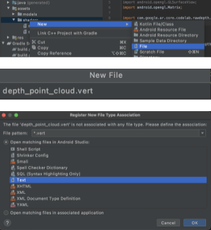
新しい .vert ファイルに次のコードを追加します。
src/main/assets/shaders/depth_point_cloud.vert
uniform mat4 u_ModelViewProjection;
uniform float u_PointSize;

attribute vec4 a_Position;

varying vec4 v_Color;

// Return an interpolated color in a 6 degree polynomial interpolation.
vec3 GetPolynomialColor(in float x,
  in vec4 kRedVec4, in vec4 kGreenVec4, in vec4 kBlueVec4,
  in vec2 kRedVec2, in vec2 kGreenVec2, in vec2 kBlueVec2) {
  // Moves the color space a little bit to avoid pure red.
  // Removes this line for more contrast.
  x = clamp(x * 0.9 + 0.03, 0.0, 1.0);
  vec4 v4 = vec4(1.0, x, x * x, x * x * x);
  vec2 v2 = v4.zw * v4.z;
  return vec3(
    dot(v4, kRedVec4) + dot(v2, kRedVec2),
    dot(v4, kGreenVec4) + dot(v2, kGreenVec2),
    dot(v4, kBlueVec4) + dot(v2, kBlueVec2)
  );
}

// Return a smooth Percept colormap based upon the Turbo colormap.
vec3 PerceptColormap(in float x) {
  const vec4 kRedVec4 = vec4(0.55305649, 3.00913185, -5.46192616, -11.11819092);
  const vec4 kGreenVec4 = vec4(0.16207513, 0.17712472, 15.24091500, -36.50657960);
  const vec4 kBlueVec4 = vec4(-0.05195877, 5.18000081, -30.94853351, 81.96403246);
  const vec2 kRedVec2 = vec2(27.81927491, -14.87899417);
  const vec2 kGreenVec2 = vec2(25.95549545, -5.02738237);
  const vec2 kBlueVec2 = vec2(-86.53476570, 30.23299484);
  const float kInvalidDepthThreshold = 0.01;
  return step(kInvalidDepthThreshold, x) *
         GetPolynomialColor(x, kRedVec4, kGreenVec4, kBlueVec4,
                            kRedVec2, kGreenVec2, kBlueVec2);
}

void main() {
   // Color the pointcloud by height.
   float kMinHeightMeters = -2.0f;
   float kMaxHeightMeters = 2.0f;
   float normalizedHeight = clamp((a_Position.y - kMinHeightMeters) / (kMaxHeightMeters - kMinHeightMeters), 0.0, 1.0);
   v_Color = vec4(PerceptColormap(normalizedHeight), 1.0);
   gl_Position = u_ModelViewProjection * vec4(a_Position.xyz, 1.0);
   gl_PointSize = u_PointSize;
}
このシェーダーでは視覚化を改善する目的で Turbo カラーマップを使用します。次の手順を実行します。
- 各ポイントの標高(ワールド座標の y 軸)を取得します。
- その標高に関連付けられた色を計算します(赤=低、青=高)。
- 各ポイントの画面上の位置を計算します。
DepthRenderer.update()メソッドで定義されている各ポイントのサイズ(ピクセル単位)を設定します。
このセクションの手順を繰り返して、同じディレクトリにフラグメント シェーダーを作成し、depth_point_cloud.frag という名前を付けます。
次に、この新しいファイルに次のコードを追加して、頂点シェーダーで定義されているように、各ポイントを単一の均一な色の頂点としてレンダリングします。
src/main/assets/shaders/depth_point_cloud.frag
precision mediump float;
varying vec4 v_Color;

void main() {
    gl_FragColor = v_Color;
}
このレンダリングを適用するには、RawDepthCodelabActivity 内に DepthRenderer クラスへの呼び出しを追加します。
src/main/java/com/google/ar/core/codelab/common/rendering/RawDepthCodelabActivity.java
import com.google.ar.core.codelab.common.rendering.DepthRenderer;
クラスの先頭で、backgroundRenderer の横に非公開メンバーを追加します。
private final DepthRenderer depthRenderer = new DepthRenderer();
depthRenderer は、既存の backgroundRenderer と同様に、RawDepthCodelabActivity.onSurfaceCreated() 内で初期化する必要があります。
depthRenderer.createOnGlThread(/*context=*/ this);
onDrawFrame 内の try-catch ブロックの末尾に次のコードを追加して、現在のフレームの最新の深度を表示します。
// Visualize depth points.
depthRenderer.update(points);
depthRenderer.draw(camera);
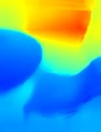
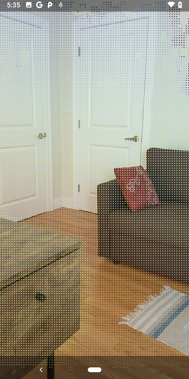
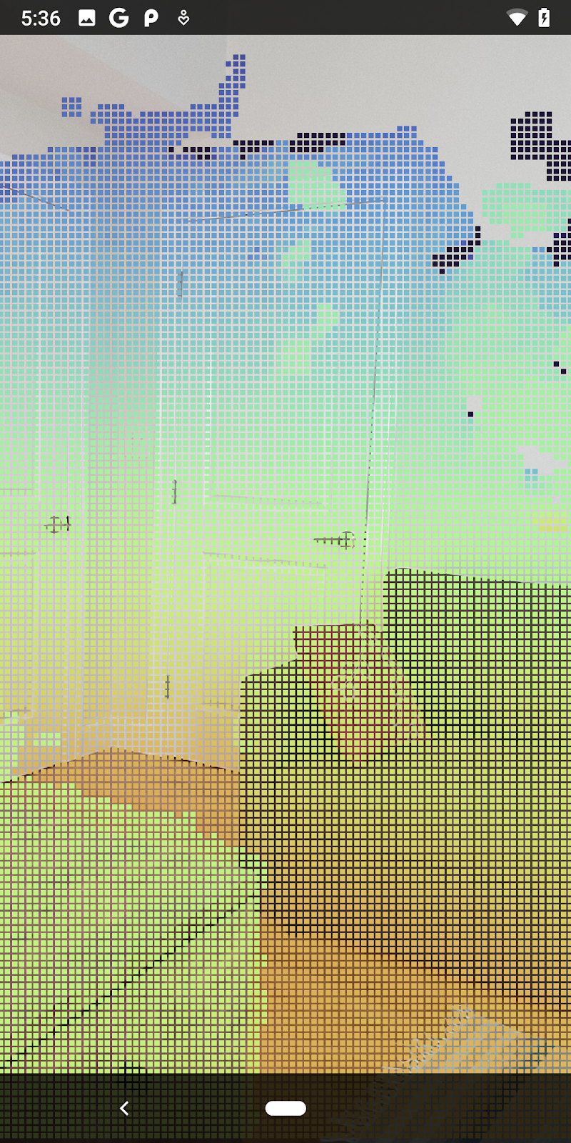
これらの変更により、アプリが正常にビルドされ、深度ポイント クラウドが表示されるようになります。
| 生深度ポイント クラウドの可視化の例
|
7. 3D ポイント クラウドを分析する(パート 3)
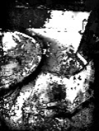
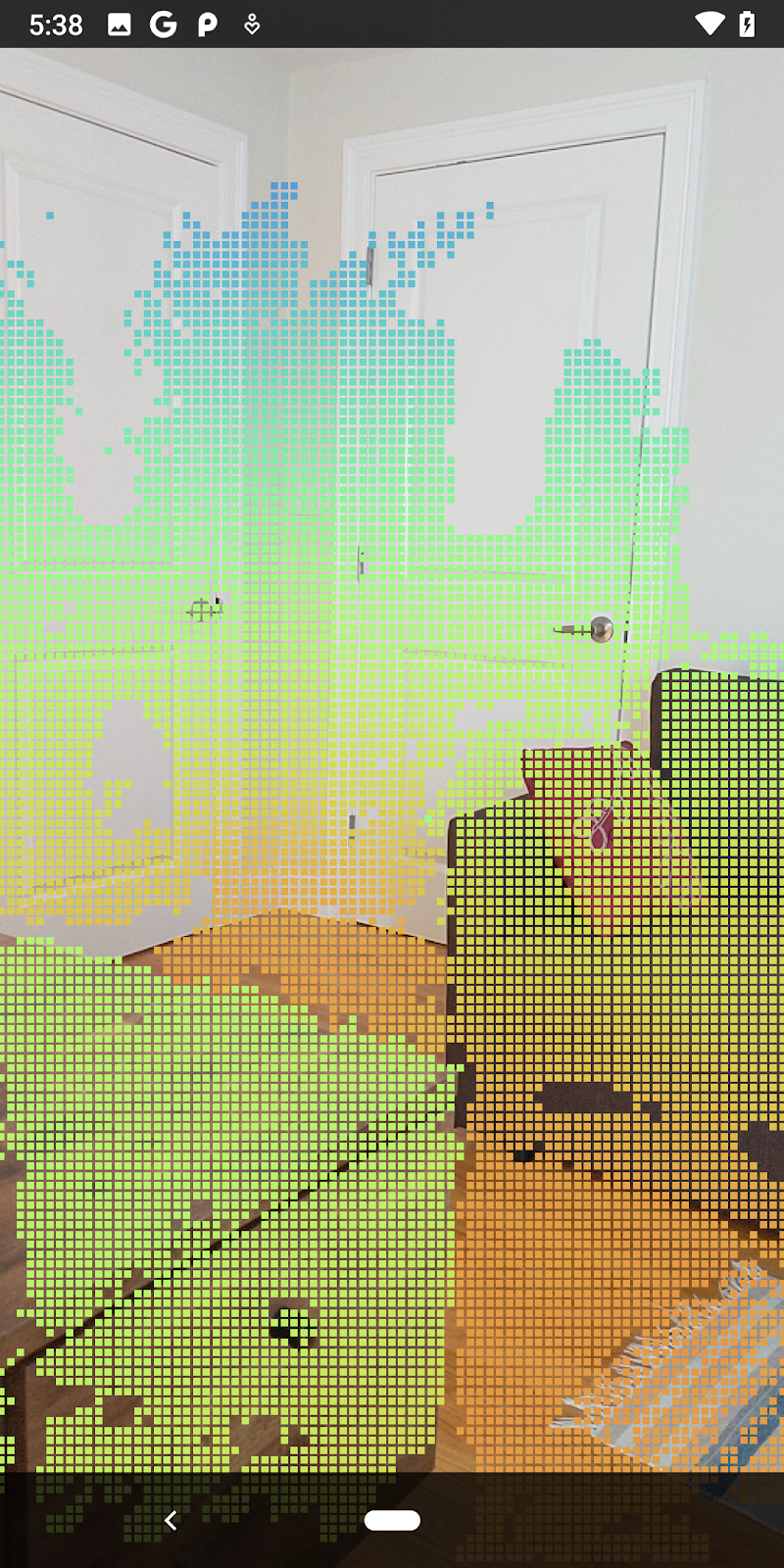
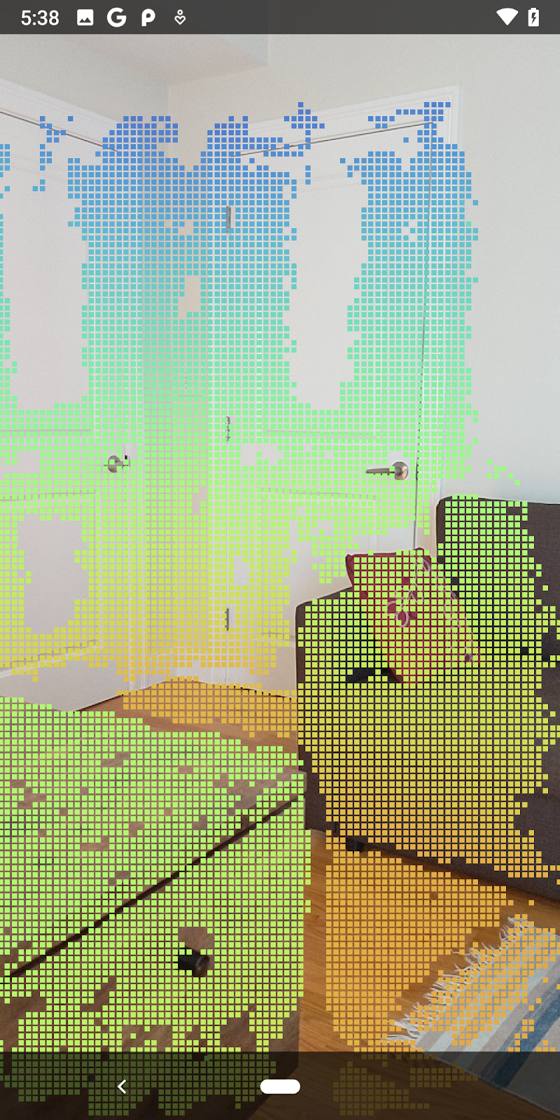
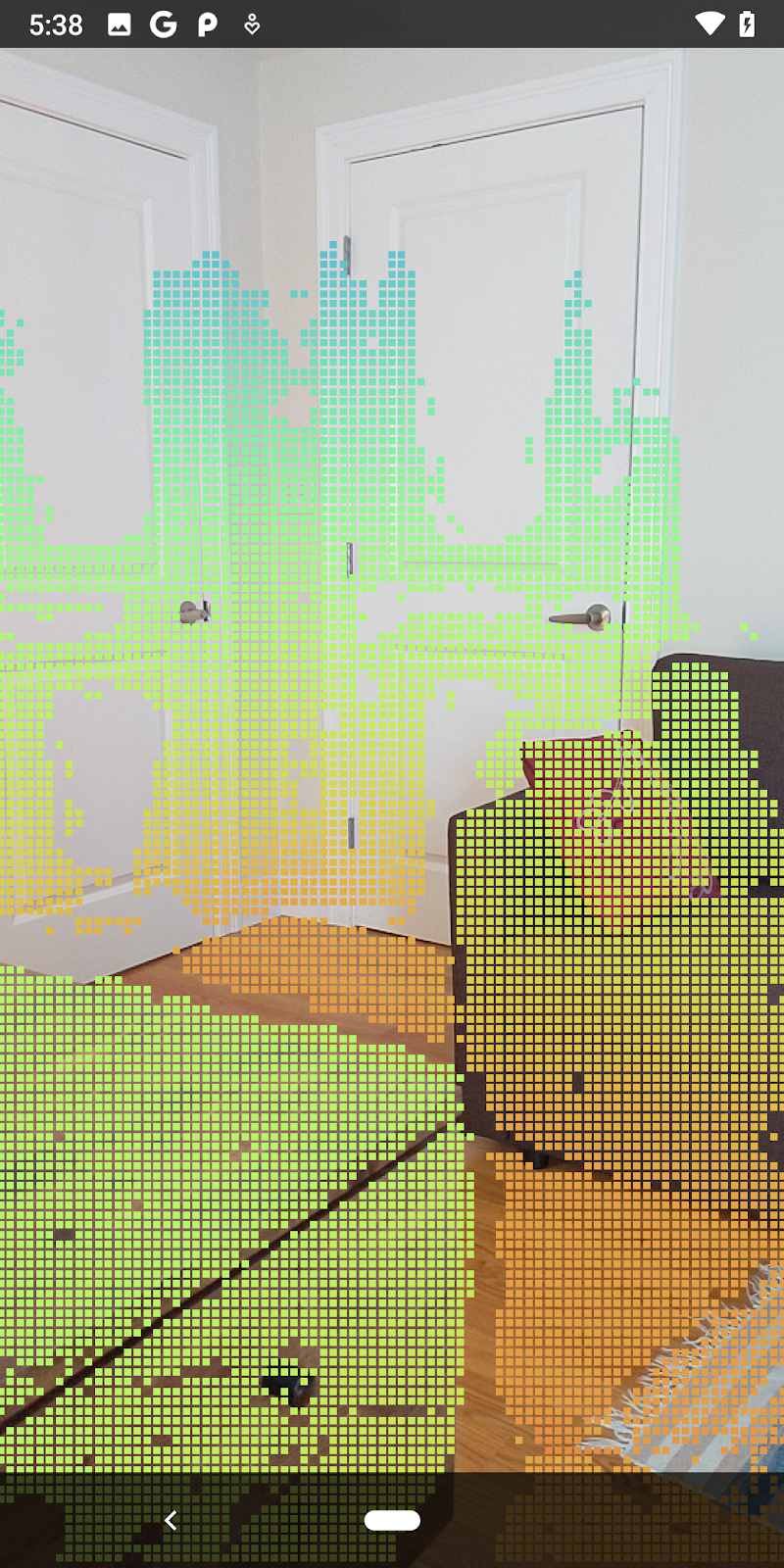
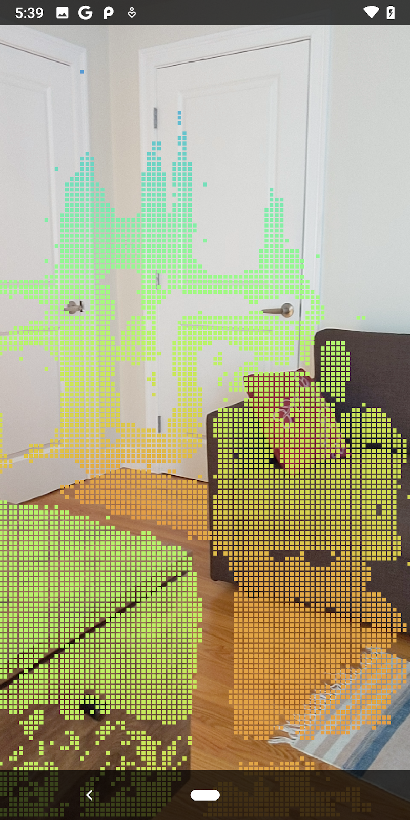
AR セッションに深度データが存在することを確認したら、深度データを分析できます。深度の分析に重要なツールは、各ピクセルの信頼度の値です。信頼値を使用して 3D ポイントクラウドを分析します。
信頼度の低いピクセルを無効にする
各深度ピクセルの信頼値を取得し、DepthData 内の各ポイントとともに保存しましたが、まだ使用していません。
confidenceNormalized の値の範囲は 0 ~ 1 です。0 は信頼度が低いことを示し、1 は信頼度が完全に高いことを示します。DepthData クラスの convertRawDepthImagesTo3dPointBuffer() メソッドを変更して、信頼度が低すぎて役に立たないピクセルを保存しないようにします。
final float confidenceNormalized = ((float) (confidencePixelValue & 0xff)) / 255.0f;

// ******** New code to add ************
if (confidenceNormalized < 0.3) {
   // Ignores "low-confidence" pixels.
   continue;
}
// ******** End of new code to add *********
信頼度のさまざまなしきい値を試して、各レベルで保持される深度ポイントの数を確認します。
|
|
|
|
|
信頼度 >= 0.1 | 信頼度 >= 0.3 | 信頼度 >= 0.5 | 信頼度 >= 0.7 | 信頼度 >= 0.9 |
距離でピクセルをフィルタする
距離で深度ピクセルをフィルタすることもできます。次のステップでは、カメラに近いジオメトリを扱います。パフォーマンスを最適化するために、遠すぎるポイントは無視できます。
追加した信頼度チェック コードを次のように更新します。
src/main/java/com/google/ar/core/codelab/rawdepth/DepthData.java
if (confidenceNormalized < 0.3 || depthMeters > 1.5) {
    // Ignore "low-confidence" pixels or depth that is too far away.
   continue;
 }
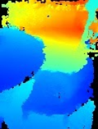
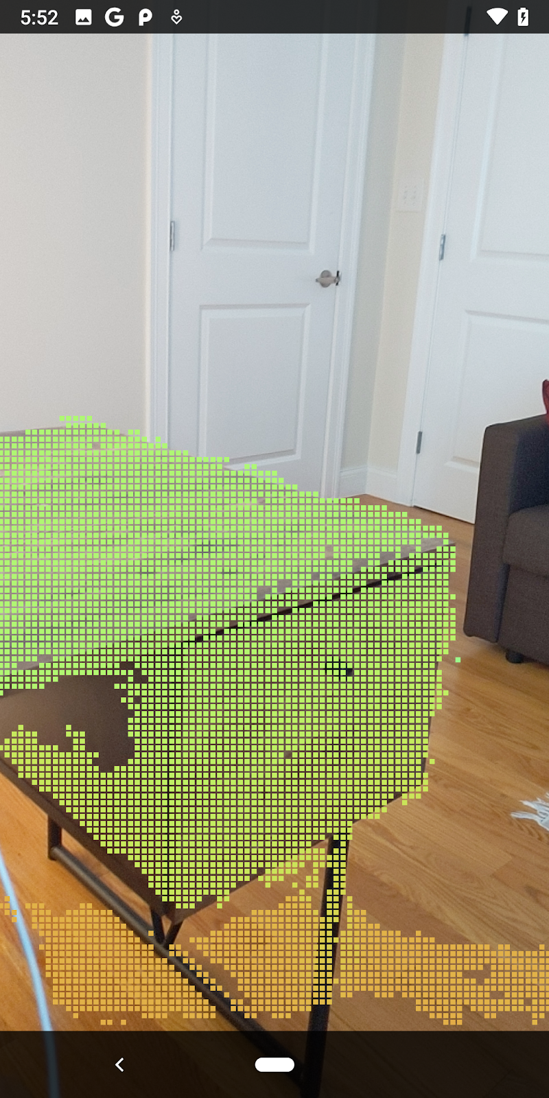
これで、信頼度が高いポイントと近いポイントのみが表示されます。
| 距離フィルタリングポイント クラウドをカメラから 1.5 メートル以内に制限します。 |
3D ポイントと平面を比較する
ジオメトリの 3D ポイントと平面を比較し、それらを使用して相互にフィルタリングできます。たとえば、観測された AR 平面に近いポイントを削除できます。
このステップでは、環境内のオブジェクトのサーフェスを表す傾向がある「非平面」ポイントのみが残ります。DepthData クラスの末尾に filterUsingPlanes() メソッドを追加します。このメソッドは既存の点を反復処理し、各点を各平面に対してチェックして、拡張現実平面に近すぎる点を無効にします。これにより、シーン内のオブジェクトをハイライトする非平面領域が残ります。
src/main/java/com/google/ar/core/codelab/rawdepth/DepthData.java
    public static void filterUsingPlanes(FloatBuffer points, Collection<Plane> allPlanes) {
        float[] planeNormal = new float[3];

        // Allocate the output buffer.
        int numPoints = points.remaining() / DepthData.FLOATS_PER_POINT;

        // Check each plane against each point.
        for (Plane plane : allPlanes) {
            if (plane.getTrackingState() != TrackingState.TRACKING || plane.getSubsumedBy() != null) {
                continue;
            }

            // Compute the normal vector of the plane.
            Pose planePose = plane.getCenterPose();
            planePose.getTransformedAxis(1, 1.0f, planeNormal, 0);

            // Filter points that are too close to the plane.
            for (int index = 0; index < numPoints; ++index) {
                // Retrieves the next point.
                final float x = points.get(FLOATS_PER_POINT * index);
                final float y = points.get(FLOATS_PER_POINT * index + 1);
                final float z = points.get(FLOATS_PER_POINT * index + 2);

                // Transform point to be in world coordinates, to match plane info.
                float distance = (x - planePose.tx()) * planeNormal[0]
                        + (y - planePose.ty()) * planeNormal[1]
                        + (z - planePose.tz()) * planeNormal[2];
                // Controls the size of objects detected.
                // Smaller values mean smaller objects will be kept.
                // Larger values will only allow detection of larger objects, but also helps reduce noise.
                if (Math.abs(distance) > 0.03) {
                    continue;  // Keep this point, since it's far enough away from the plane.
                }

                // Invalidate points that are too close to planar surfaces.
                points.put(FLOATS_PER_POINT * index, 0);
                points.put(FLOATS_PER_POINT * index + 1, 0);
                points.put(FLOATS_PER_POINT * index + 2, 0);
                points.put(FLOATS_PER_POINT * index + 3, 0);
            }
        }
    }
このメソッドは、onDrawFrame メソッドの RawDepthCodelabActivity に追加できます。
//  ********** New code to add ************
  // Filter the depth data.
  DepthData.filterUsingPlanes(points, session.getAllTrackables(Plane.class));
//  ********** End new code to add *******

  // Visualize depth points.
  depthRenderer.update(points);
  depthRenderer.draw(camera);
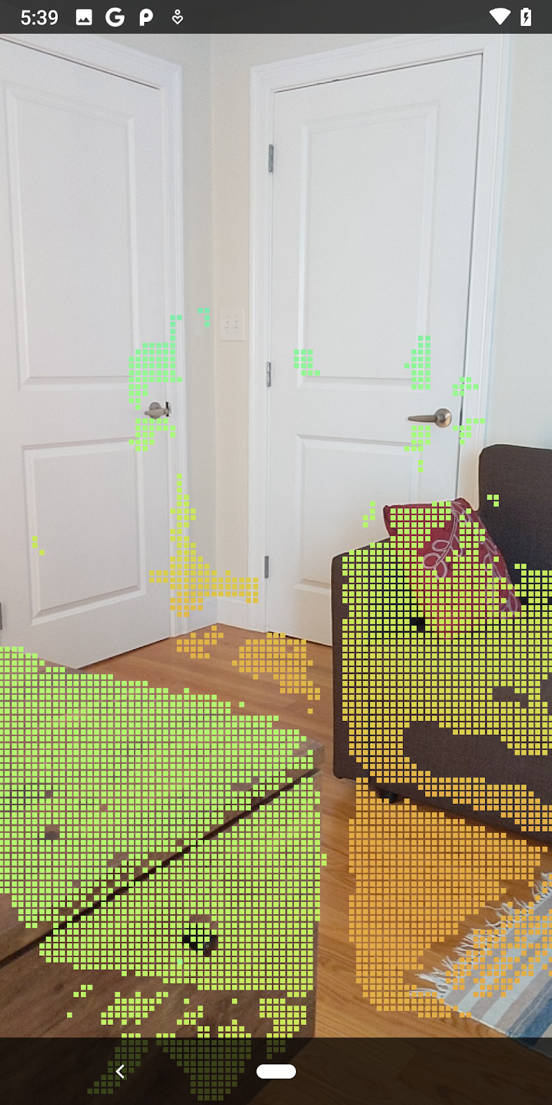
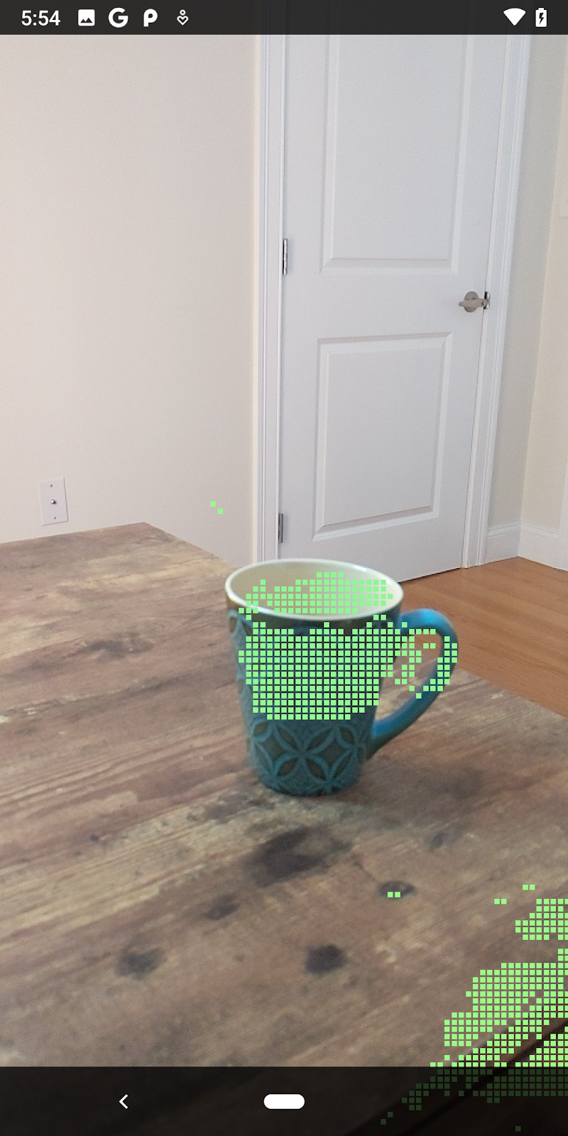
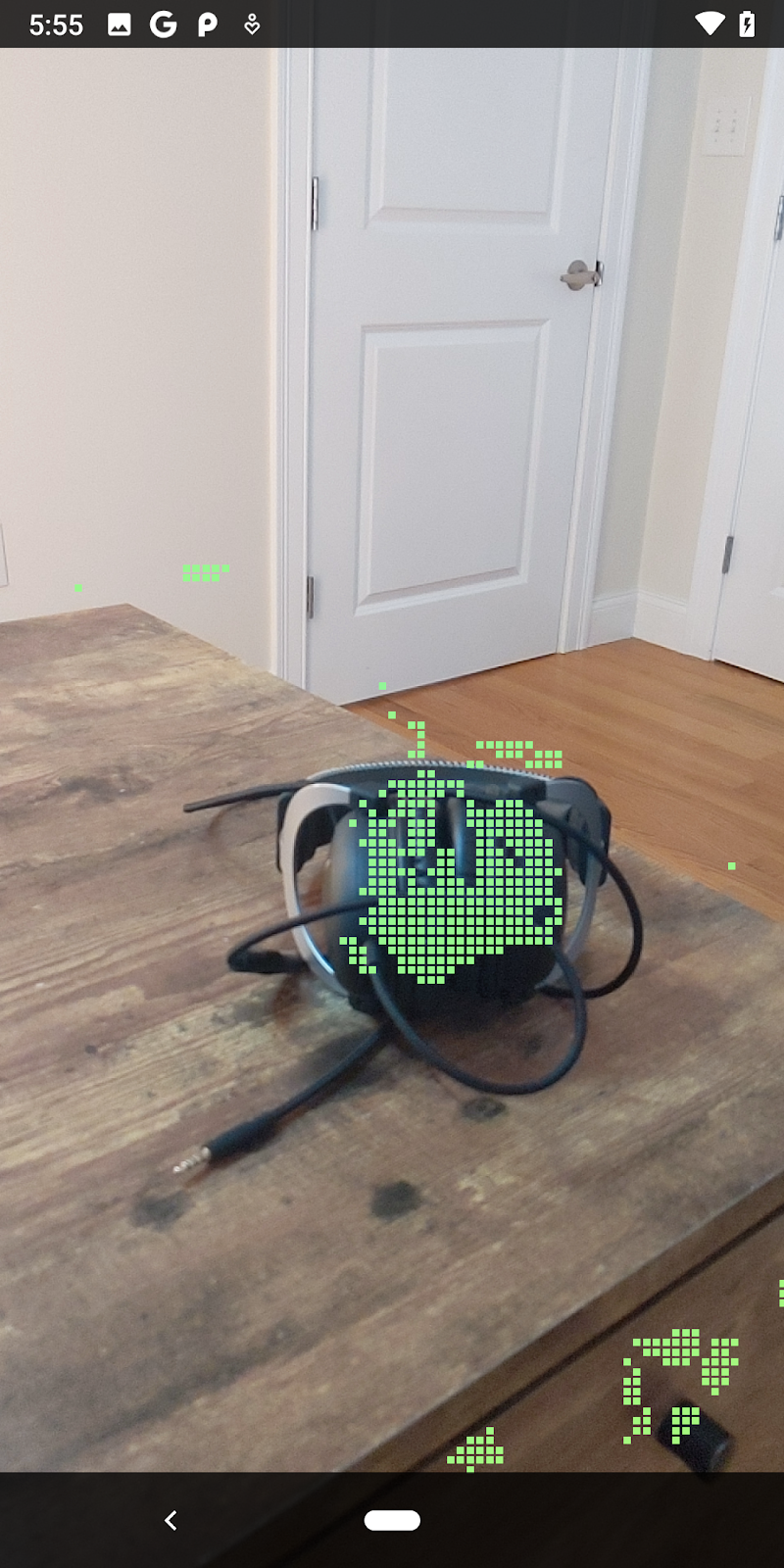
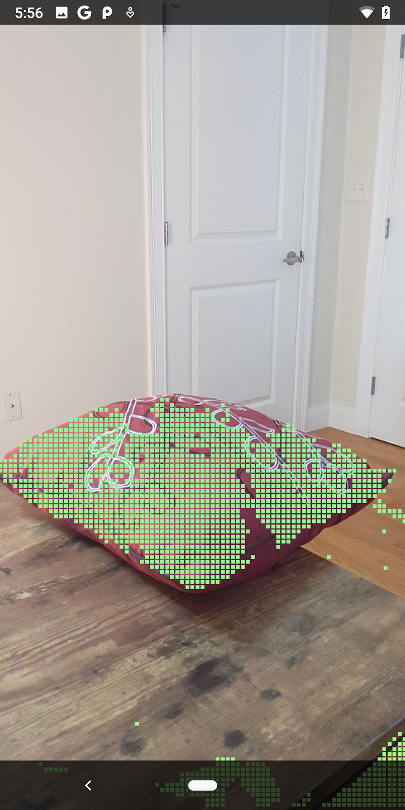
この Codelab を実行すると、ポイントのサブセットがレンダリングされます。これらの点は、オブジェクトが置かれている平らな面を無視して、シーン内のオブジェクトを表します。これらのデータを使用して、ポイントをクラスタリングすることでオブジェクトのサイズと位置を推定できます。
|
|
|
|
紅茶 | マイク | ヘッドフォン | Pillow |
クラスタ ポイント
この Codelab には、非常に単純なポイント クラウド クラスタリング アルゴリズムが含まれています。取得したポイントクラウドを軸に沿ったバウンディング ボックスで定義されたクラスタにグループ化するように、Codelab を更新します。
src/main/java/com/google/ar/core/codelab/rawdepth/RawDepthCodelabActivity.java
import com.google.ar.core.codelab.common.helpers.AABB;
import com.google.ar.core.codelab.common.helpers.PointClusteringHelper;
import com.google.ar.core.codelab.common.rendering.BoxRenderer;
import java.util.List;
このクラスのファイルの先頭に、他のレンダラとともに BoxRenderer を追加します。
private final BoxRenderer boxRenderer = new BoxRenderer();
また、onSurfaceCreated() メソッド内で、他のレンダラとともに次の行を追加します。
boxRenderer.createOnGlThread(/*context=*/this);
最後に、RawDepthCodelabActivity 内の onDrawFrame() に次の行を追加して、取得したポイントクラウドをクラスタにグループ化し、結果を軸に沿ったバウンディング ボックスとしてレンダリングします。
      // Visualize depth points.
      depthRenderer.update(points);
      depthRenderer.draw(camera);

// ************ New code to add ***************

      // Draw boxes around clusters of points.
      PointClusteringHelper clusteringHelper = new PointClusteringHelper(points);
      List<AABB> clusters = clusteringHelper.findClusters();
      for (AABB aabb : clusters) {
        boxRenderer.draw(aabb, camera);
      }

// ************ End new code to add ***************
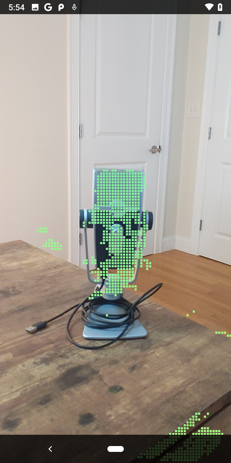
|
|
|
|
紅茶 | マイク | ヘッドフォン | Pillow |
ARCore セッションを通じて Raw Depth を取得し、深度情報を 3D ポイントクラウドに変換して、それらのポイントに対して基本的なフィルタリングとレンダリングのオペレーションを実行できるようになりました。
8. ビルド、実行、テスト
アプリをビルド、実行、テストします。
アプリをビルドして実行する
以下の手順に沿ってアプリをビルドして実行します。
- USB 経由で ARCore 対応デバイスに接続します。
- メニューバーの ► ボタンを使用してプロジェクトを実行します。
- アプリがビルドされ、デバイスにデプロイされるのを待ちます。
デバイスに初めてアプリをデプロイする場合は、
[USB デバッグを許可しますか?]
とデバイスで尋ねられるので、[OK] を選択して続行します。
デバイスで初めてアプリを実行する場合には、アプリにデバイスのカメラを使用する権限があるか尋ねられます。AR 機能を引き続き使用するには、アクセスを許可する必要があります。
アプリのテスト
アプリを実行するとき、デバイスをつかんで、空間内で動かし、領域をゆっくりスキャンすることで、基本的な動作をテストできます。次のステップに進む前に、少なくとも 10 秒間データを収集して、複数の方向から領域をスキャンします。
9. 完了
これで、Google の ARCore Raw Depth API を使用して初めての深度ベースの拡張現実アプリを作成して実行できました。皆様がどのようなものを構築されるか楽しみにしております。
10. トラブルシューティング
開発用 Android デバイスのセットアップ
- USB ケーブルで、デバイスと開発マシンを接続します。Windows を使用して開発する場合、デバイスに適切な USB ドライバのインストールが必要になる場合があります。
- 次の手順に沿って、[開発者向けオプション] ウィンドウで、[USB デバッグ] を有効にします。
- 設定アプリを開きます。
- デバイスで Android 8.0 以降が使用されている場合は、[System] を選択します。
- 下にスクロールして、[デバイス情報] を選択します。
- 一番下までスクロールして [ビルド番号] を 7 回タップします。
- 前の画面に戻り、一番下までスクロールして [開発者向けオプション] をタップします。
- [開発者向けオプション] ウィンドウで、下にスクロールして [USB デバッグ] を有効にします。
この手順の詳細については、Google の Android デベロッパー ウェブサイトをご覧ください。
ライセンス関連のビルドエラー
ライセンス関連のビルドエラーが発生した場合(Failed to install the following Android SDK packages as some licences have not been accepted)、次のコマンドでライセンスを確認して承認できます。
cd <path to Android SDK>
tools/bin/sdkmanager --licenses