
1. 简介
ARCore 是用于在移动设备上构建增强现实 (AR) 应用的平台。Google 的 ARCore Depth API 支持访问 ARCore 会话中每一帧的深度图像。深度图像中的每个像素提供了从相机到环境的距离测量值。
Raw Depth API 提供的深度图像不会通过旨在对结果进行平滑和插值运算的屏幕空间过滤操作传递。这些值在几何上较为准确,但可能包含缺失的数据,并且与相关相机图像的对齐度较低。
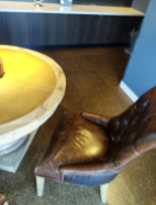
此 Codelab 介绍了如何使用 Raw Depth API 对场景执行 3D 几何图形分析。您将构建一款简单的 AR 应用,该应用使用原始深度数据来检测并直观呈现世界的几何图形。
只有部分支持 ARCore 的设备支持 Depth API 和 Raw Depth API。Depth API 仅适用于 Android。
构建内容
在此 Codelab 中,您将构建一个应用,该应用使用每一帧的原始深度图像对周围世界执行几何分析。此应用将:
- 检查目标设备是否支持深度。
- 检索每个相机帧的原始深度图像。
- 将原始深度图像重新投影到 3D 点中,并根据置信度和几何图形对这些点进行过滤。
- 使用原始深度点云来分割感兴趣的 3D 对象。
|
快速预览您将构建的内容。 |
注意:如果您在操作过程中遇到任何问题,请跳到最后一部分,查看相关的问题排查提示。
2. 前提条件
您需要有特定的软硬件才能完成此 Codelab。
硬件要求
- 一台启用了 USB 调试的支持 ARCore 的设备,并通过 USB 线连接到开发机器。此设备还必须支持 Depth API。
软件要求
- ARCore SDK 1.31.0 或更高版本。
- 一台安装了 Android Studio(v4.0.1 或更高版本)的开发机器。
3. 设置
设置开发机器
使用 USB 线将 ARCore 设备连接到计算机。确保您的设备允许执行 USB 调试。打开一个终端并运行 adb devices,如下所示:
adb devices

List of devices attached
<DEVICE_SERIAL_NUMBER>    device
<DEVICE_SERIAL_NUMBER> 将是与您的设备对应的独一无二的字符串。请在确保设备的序列号准确无误后再继续。
下载并安装代码
您可以克隆代码库:
git clone https://github.com/googlecodelabs/arcore-rawdepthapi
或者下载 ZIP 文件并解压缩:
请按照以下步骤开始使用代码。
- 启动 Android Studio,然后选择 Open an existing Android Studio project。
- 导航到存储原始深度 ZIP 文件的本地目录。
- 双击
arcore_rawdepthapi_codelab目录。
arcore_rawdepthapi_codelab 目录是包含多个模块的单个 Gradle 项目。如果“Project”窗格中尚未显示 Android Studio 左上角的“Project”窗格,请点击下拉菜单中的 Projects。
结果应如下所示:
| 此项目包含以下模块:
|
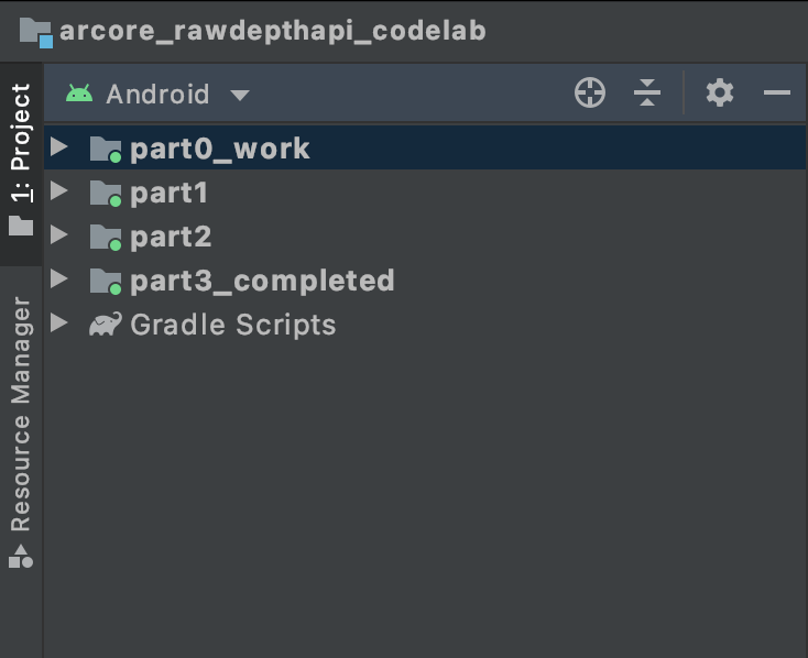
您将在 part0_work 模块中进行修改。我们还提供了 Codelab 的各个部分的完整解决方案。每个模块都是一个可构建的应用。
4. 运行起始应用
请按照以下步骤运行原始深度起始应用。
- 导航到 Run >运行...>“part0_work”。
- 在 Select Deployment Target 对话框中,从 Connected Devices 列表中选择您的设备,然后点击 OK。
Android Studio 将构建初始应用并在您的设备上运行该应用。
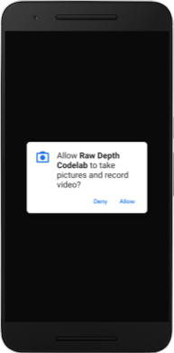
| 您首次运行该应用时,它会请求 CAMERA 权限。点按 Allow 以继续。 |
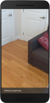
| 目前,该应用不执行任何操作。这是最基本的 AR 应用,显示场景的相机视图,但不执行任何其他操作。现有代码类似于使用 ARCore SDK 发布的 Hello AR 示例。 |
接下来,您将使用 Raw Depth API 检索周围场景的几何图形。
5. 设置原始 Depth API(第 1 部分)
确保目标设备支持深度
并非所有支持 ARCore 的设备都可以运行 Depth API。请先确保目标设备支持 Depth,然后再在 RawDepthCodelabActivity.java 的 onResume() 函数内向应用添加功能(该函数会创建一个新会话)。
找到现有代码:
// Create the ARCore session.
session = new Session(/* context= */ this);
请更新您的代码,以确保应用仅在可支持 Depth API 的设备上运行。
// Create the ARCore session.
session = new Session(/* context= */ this);
if (!session.isDepthModeSupported(Config.DepthMode.RAW_DEPTH_ONLY)) {
  message =
     "This device does not support the ARCore Raw Depth API. See" +
     "https://developers.google.com/ar/devices for
     a list of devices that do.";
}
启用原始深度
Raw Depth API 提供未平滑处理的深度图像,以及包含原始深度图像中每个像素的深度置信度的对应置信度图像。通过更新您刚刚修改的 try-catch 语句下的以下代码来启用原始深度。
try {
  // ************ New code to add ***************
  // Enable raw depth estimation and auto focus mode while ARCore is running.
  Config config = session.getConfig();
  config.setDepthMode(Config.DepthMode.RAW_DEPTH_ONLY);
  config.setFocusMode(Config.FocusMode.AUTO);
  session.configure(config);
  // ************ End new code to add ***************
  session.resume();
} catch (CameraNotAvailableException e) {
  messageSnackbarHelper.showError(this, "Camera not available. Try restarting the app.");
  session = null;
  return;
}
现在,AR 会话已正确配置,应用就可以使用基于深度的功能了。
调用 Depth API
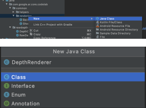
接下来,调用 Depth API 以检索每一帧的深度图像。通过创建新文件将深度数据封装到新类中。右键点击 rawdepth 文件夹,然后选择 New > Java Class。这会创建一个空白文件。将以下代码添加到此类:
src/main/java/com/google/ar/core/codelab/rawdepth/DepthData.java
package com.google.ar.core.codelab.rawdepth;

import android.media.Image;
import android.opengl.Matrix;

import com.google.ar.core.Anchor;
import com.google.ar.core.CameraIntrinsics;
import com.google.ar.core.Frame;
import com.google.ar.core.exceptions.NotYetAvailableException;

import java.nio.ByteBuffer;
import java.nio.ByteOrder;
import java.nio.FloatBuffer;
import java.nio.ShortBuffer;

/**
 * Convert depth data from ARCore depth images to 3D pointclouds. Points are added by calling the
 * Raw Depth API, and reprojected into 3D space.
 */
public class DepthData {
    public static final int FLOATS_PER_POINT = 4; // X,Y,Z,confidence.

}
此类用于将深度图像转换为点云。Pointcloud 表示场景几何图形,其中包含一系列点,其中每个点都有一个 3D 坐标 (x, y, z) 和 0 到 1 范围内的置信度值。
通过在类底部添加 create() 方法,添加调用,以便使用 Raw Depth API 填充这些值。此方法会查询最新的深度和置信度图像,并存储生成的点云。深度和置信度图片将具有匹配数据。
public static FloatBuffer create(Frame frame, Anchor cameraPoseAnchor) {
    try {
        Image depthImage = frame.acquireRawDepthImage16Bits();
        Image confidenceImage = frame.acquireRawDepthConfidenceImage();

        // Retrieve the intrinsic camera parameters corresponding to the depth image to
        // transform 2D depth pixels into 3D points. See more information about the depth values
        // at
        // https://developers.google.com/ar/develop/java/depth/overview#understand-depth-values.

        final CameraIntrinsics intrinsics = frame.getCamera().getTextureIntrinsics();
        float[] modelMatrix = new float[16];
        cameraPoseAnchor.getPose().toMatrix(modelMatrix, 0);
        final FloatBuffer points = convertRawDepthImagesTo3dPointBuffer(
                depthImage, confidenceImage, intrinsics, modelMatrix);

        depthImage.close();
        confidenceImage.close();

        return points;
    } catch (NotYetAvailableException e) {
        // This normally means that depth data is not available yet.
        // This is normal, so you don't have to spam the logcat with this.
    }
    return null;
}
|
|
|
|
|
|
|
|
此时,该代码还会存储镜头锚点,以便通过调用辅助方法 convertRawDepthImagesTo3dPointBuffer() 将深度信息转换为世界坐标。此辅助方法会获取深度图像中的每个像素,并使用相机内联函数将深度投影到相对于相机的 3D 点中。然后,使用镜头锚点将点的位置转换为世界坐标。存在的每个像素都将转换为 3D 点(以米为单位),并与其置信度一起存储。
将以下辅助方法添加到 DepthData.java 中:
/** Apply camera intrinsics to convert depth image into a 3D pointcloud. */
    private static FloatBuffer convertRawDepthImagesTo3dPointBuffer(
            Image depth, Image confidence, CameraIntrinsics cameraTextureIntrinsics, float[] modelMatrix) {
        // Java uses big endian so change the endianness to ensure
        // that the depth data is in the correct byte order.
        final Image.Plane depthImagePlane = depth.getPlanes()[0];
        ByteBuffer depthByteBufferOriginal = depthImagePlane.getBuffer();
        ByteBuffer depthByteBuffer = ByteBuffer.allocate(depthByteBufferOriginal.capacity());
        depthByteBuffer.order(ByteOrder.LITTLE_ENDIAN);
        while (depthByteBufferOriginal.hasRemaining()) {
            depthByteBuffer.put(depthByteBufferOriginal.get());
        }
        depthByteBuffer.rewind();
        ShortBuffer depthBuffer = depthByteBuffer.asShortBuffer();

        final Image.Plane confidenceImagePlane = confidence.getPlanes()[0];
        ByteBuffer confidenceBufferOriginal = confidenceImagePlane.getBuffer();
        ByteBuffer confidenceBuffer = ByteBuffer.allocate(confidenceBufferOriginal.capacity());
        confidenceBuffer.order(ByteOrder.LITTLE_ENDIAN);
        while (confidenceBufferOriginal.hasRemaining()) {
            confidenceBuffer.put(confidenceBufferOriginal.get());
        }
        confidenceBuffer.rewind();

        // To transform 2D depth pixels into 3D points, retrieve the intrinsic camera parameters
        // corresponding to the depth image. See more information about the depth values at
        // https://developers.google.com/ar/develop/java/depth/overview#understand-depth-values.
        final int[] intrinsicsDimensions = cameraTextureIntrinsics.getImageDimensions();
        final int depthWidth = depth.getWidth();
        final int depthHeight = depth.getHeight();
        final float fx =
                cameraTextureIntrinsics.getFocalLength()[0] * depthWidth / intrinsicsDimensions[0];
        final float fy =
                cameraTextureIntrinsics.getFocalLength()[1] * depthHeight / intrinsicsDimensions[1];
        final float cx =
                cameraTextureIntrinsics.getPrincipalPoint()[0] * depthWidth / intrinsicsDimensions[0];
        final float cy =
                cameraTextureIntrinsics.getPrincipalPoint()[1] * depthHeight / intrinsicsDimensions[1];

        // Allocate the destination point buffer. If the number of depth pixels is larger than
        // `maxNumberOfPointsToRender` we uniformly subsample. The raw depth image may have
        // different resolutions on different devices.
        final float maxNumberOfPointsToRender = 20000;
        int step = (int) Math.ceil(Math.sqrt(depthWidth * depthHeight / maxNumberOfPointsToRender));

        FloatBuffer points = FloatBuffer.allocate(depthWidth / step * depthHeight / step * FLOATS_PER_POINT);
        float[] pointCamera = new float[4];
        float[] pointWorld = new float[4];

        for (int y = 0; y < depthHeight; y += step) {
            for (int x = 0; x < depthWidth; x += step) {
                // Depth images are tightly packed, so it's OK to not use row and pixel strides.
                int depthMillimeters = depthBuffer.get(y * depthWidth + x); // Depth image pixels are in mm.
                if (depthMillimeters == 0) {
                    // Pixels with value zero are invalid, meaning depth estimates are missing from
                    // this location.
                    continue;
                }
                final float depthMeters = depthMillimeters / 1000.0f; // Depth image pixels are in mm.

                // Retrieve the confidence value for this pixel.
                final byte confidencePixelValue =
                        confidenceBuffer.get(
                                y * confidenceImagePlane.getRowStride()
                                        + x * confidenceImagePlane.getPixelStride());
                final float confidenceNormalized = ((float) (confidencePixelValue & 0xff)) / 255.0f;

                // Unproject the depth into a 3D point in camera coordinates.
                pointCamera[0] = depthMeters * (x - cx) / fx;
                pointCamera[1] = depthMeters * (cy - y) / fy;
                pointCamera[2] = -depthMeters;
                pointCamera[3] = 1;

                // Apply model matrix to transform point into world coordinates.
                Matrix.multiplyMV(pointWorld, 0, modelMatrix, 0, pointCamera, 0);
                points.put(pointWorld[0]); // X.
                points.put(pointWorld[1]); // Y.
                points.put(pointWorld[2]); // Z.
                points.put(confidenceNormalized);
            }
        }

        points.rewind();
        return points;
    }
获取每一帧的最新原始深度数据
修改应用以检索深度信息,并将其与每个姿势的世界坐标对齐。
在 RawDepthCodelabActivity.java 中的 onDrawFrame() 方法中找到现有代码行:
Frame frame = session.update();
Camera camera = frame.getCamera();

// If the frame is ready, render the camera preview image to the GL surface.
backgroundRenderer.draw(frame);
在它正下方添加以下几行:
// Retrieve the depth data for this frame.
FloatBuffer points = DepthData.create(frame, session.createAnchor(camera.getPose()));
if (points == null) {
  return;
}

if (messageSnackbarHelper.isShowing() && points != null) {
  messageSnackbarHelper.hide(this);
}
6. 渲染深度数据(第 2 部分)
现在,您已经有了深度点云,是时候查看数据在屏幕上渲染的效果了。
添加渲染程序以直观呈现深度点
添加渲染程序以直观呈现深度点。
首先,添加一个用于包含呈现逻辑的新类。此类会执行 OpenGL 操作以初始化着色器,从而直观呈现深度点云。
| 添加 DepthRenderer 类
|
使用以下代码填充此类:
src/main/java/com/google/ar/core/codelab/common/rendering/DepthRenderer.java
package com.google.ar.core.codelab.common.rendering;

import android.content.Context;
import android.opengl.GLES20;
import android.opengl.Matrix;

import com.google.ar.core.Camera;
import com.google.ar.core.codelab.rawdepth.DepthData;

import java.io.IOException;
import java.nio.FloatBuffer;

public class DepthRenderer {
    private static final String TAG = DepthRenderer.class.getSimpleName();

    // Shader names.
    private static final String VERTEX_SHADER_NAME = "shaders/depth_point_cloud.vert";
    private static final String FRAGMENT_SHADER_NAME = "shaders/depth_point_cloud.frag";

    public static final int BYTES_PER_FLOAT = Float.SIZE / 8;
    private static final int BYTES_PER_POINT = BYTES_PER_FLOAT * DepthData.FLOATS_PER_POINT;
    private static final int INITIAL_BUFFER_POINTS = 1000;

    private int arrayBuffer;
    private int arrayBufferSize;

    private int programName;
    private int positionAttribute;
    private int modelViewProjectionUniform;
    private int pointSizeUniform;

    private int numPoints = 0;

    public DepthRenderer() {}

    public void createOnGlThread(Context context) throws IOException {
        ShaderUtil.checkGLError(TAG, "Bind");

        int[] buffers = new int[1];
        GLES20.glGenBuffers(1, buffers, 0);
        arrayBuffer = buffers[0];
        GLES20.glBindBuffer(GLES20.GL_ARRAY_BUFFER, arrayBuffer);

        arrayBufferSize = INITIAL_BUFFER_POINTS * BYTES_PER_POINT;
        GLES20.glBufferData(GLES20.GL_ARRAY_BUFFER, arrayBufferSize, null, GLES20.GL_DYNAMIC_DRAW);
        GLES20.glBindBuffer(GLES20.GL_ARRAY_BUFFER, 0);

        ShaderUtil.checkGLError(TAG, "Create");

        int vertexShader =
                ShaderUtil.loadGLShader(TAG, context, GLES20.GL_VERTEX_SHADER, VERTEX_SHADER_NAME);
        int fragmentShader =
                ShaderUtil.loadGLShader(TAG, context, GLES20.GL_FRAGMENT_SHADER, FRAGMENT_SHADER_NAME);

        programName = GLES20.glCreateProgram();
        GLES20.glAttachShader(programName, vertexShader);
        GLES20.glAttachShader(programName, fragmentShader);
        GLES20.glLinkProgram(programName);
        GLES20.glUseProgram(programName);

        ShaderUtil.checkGLError(TAG, "Program");

        positionAttribute = GLES20.glGetAttribLocation(programName, "a_Position");
        modelViewProjectionUniform = GLES20.glGetUniformLocation(programName, "u_ModelViewProjection");
        // Sets the point size, in pixels.
        pointSizeUniform = GLES20.glGetUniformLocation(programName, "u_PointSize");

        ShaderUtil.checkGLError(TAG, "Init complete");
    }
}
渲染深度数据
接下来,提供渲染着色器的来源。在 DepthRenderer 类的底部添加以下 update() 方法。此方法将最新的深度信息作为输入,并将点云数据复制到 GPU。
    /**
     * Update the OpenGL buffer contents to the provided point. Repeated calls with the same point
     * cloud will be ignored.
     */
    public void update(FloatBuffer points) {
        ShaderUtil.checkGLError(TAG, "Update");
        GLES20.glBindBuffer(GLES20.GL_ARRAY_BUFFER, arrayBuffer);

        // If the array buffer is not large enough to fit the new point cloud, resize it.
        points.rewind();
        numPoints = points.remaining() / DepthData.FLOATS_PER_POINT;
        if (numPoints * BYTES_PER_POINT > arrayBufferSize) {
            while (numPoints * BYTES_PER_POINT > arrayBufferSize) {
                arrayBufferSize *= 2;
            }
            GLES20.glBufferData(GLES20.GL_ARRAY_BUFFER, arrayBufferSize, null, GLES20.GL_DYNAMIC_DRAW);
        }

        GLES20.glBufferSubData(
                GLES20.GL_ARRAY_BUFFER, 0, numPoints * BYTES_PER_POINT, points);
        GLES20.glBindBuffer(GLES20.GL_ARRAY_BUFFER, 0);

        ShaderUtil.checkGLError(TAG, "Update complete");
    }
通过在 DepthRenderer 类的底部添加 draw() 方法,将最新数据绘制到屏幕上。此方法会获取 3D 点云信息,并将其投影回相机视图,以便在屏幕上渲染。
    /** Render the point cloud. The ARCore point cloud is given in world space. */
    public void draw(Camera camera) {
        float[] projectionMatrix = new float[16];
        camera.getProjectionMatrix(projectionMatrix, 0, 0.1f, 100.0f);
        float[] viewMatrix = new float[16];
        camera.getViewMatrix(viewMatrix, 0);
        float[] viewProjection = new float[16];
        Matrix.multiplyMM(viewProjection, 0, projectionMatrix, 0, viewMatrix, 0);

        ShaderUtil.checkGLError(TAG, "Draw");

        GLES20.glUseProgram(programName);
        GLES20.glEnableVertexAttribArray(positionAttribute);
        GLES20.glBindBuffer(GLES20.GL_ARRAY_BUFFER, arrayBuffer);
        GLES20.glVertexAttribPointer(positionAttribute, 4, GLES20.GL_FLOAT, false, BYTES_PER_POINT, 0);
        GLES20.glUniformMatrix4fv(modelViewProjectionUniform, 1, false, viewProjection, 0);
        // Set point size to 5 pixels.
        GLES20.glUniform1f(pointSizeUniform, 5.0f);

        GLES20.glDrawArrays(GLES20.GL_POINTS, 0, numPoints);
        GLES20.glDisableVertexAttribArray(positionAttribute);
        GLES20.glBindBuffer(GLES20.GL_ARRAY_BUFFER, 0);

        ShaderUtil.checkGLError(TAG, "Draw complete");
    }
您可以使用 pointSizeUniform 变量将点大小设置为不同的大小(以像素为单位)。在示例应用中,pointSizeUniform 设置为 5 像素。
添加新的着色器
您可以通过多种方式在应用中查看深度和显示深度数据。您将在此处添加一些着色器,并创建一个简单的颜色映射可视化效果。
将新的 .vert 和 .frag 着色器添加到 src/main/assets/shaders/ 目录中。
| 添加新的 .vert 着色器在 Android Studio 中:
|
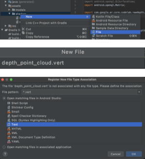
在新的 .vert 文件中,添加以下代码:
src/main/assets/shaders/depth_point_cloud.vert
uniform mat4 u_ModelViewProjection;
uniform float u_PointSize;

attribute vec4 a_Position;

varying vec4 v_Color;

// Return an interpolated color in a 6 degree polynomial interpolation.
vec3 GetPolynomialColor(in float x,
  in vec4 kRedVec4, in vec4 kGreenVec4, in vec4 kBlueVec4,
  in vec2 kRedVec2, in vec2 kGreenVec2, in vec2 kBlueVec2) {
  // Moves the color space a little bit to avoid pure red.
  // Removes this line for more contrast.
  x = clamp(x * 0.9 + 0.03, 0.0, 1.0);
  vec4 v4 = vec4(1.0, x, x * x, x * x * x);
  vec2 v2 = v4.zw * v4.z;
  return vec3(
    dot(v4, kRedVec4) + dot(v2, kRedVec2),
    dot(v4, kGreenVec4) + dot(v2, kGreenVec2),
    dot(v4, kBlueVec4) + dot(v2, kBlueVec2)
  );
}

// Return a smooth Percept colormap based upon the Turbo colormap.
vec3 PerceptColormap(in float x) {
  const vec4 kRedVec4 = vec4(0.55305649, 3.00913185, -5.46192616, -11.11819092);
  const vec4 kGreenVec4 = vec4(0.16207513, 0.17712472, 15.24091500, -36.50657960);
  const vec4 kBlueVec4 = vec4(-0.05195877, 5.18000081, -30.94853351, 81.96403246);
  const vec2 kRedVec2 = vec2(27.81927491, -14.87899417);
  const vec2 kGreenVec2 = vec2(25.95549545, -5.02738237);
  const vec2 kBlueVec2 = vec2(-86.53476570, 30.23299484);
  const float kInvalidDepthThreshold = 0.01;
  return step(kInvalidDepthThreshold, x) *
         GetPolynomialColor(x, kRedVec4, kGreenVec4, kBlueVec4,
                            kRedVec2, kGreenVec2, kBlueVec2);
}

void main() {
   // Color the pointcloud by height.
   float kMinHeightMeters = -2.0f;
   float kMaxHeightMeters = 2.0f;
   float normalizedHeight = clamp((a_Position.y - kMinHeightMeters) / (kMaxHeightMeters - kMinHeightMeters), 0.0, 1.0);
   v_Color = vec4(PerceptColormap(normalizedHeight), 1.0);
   gl_Position = u_ModelViewProjection * vec4(a_Position.xyz, 1.0);
   gl_PointSize = u_PointSize;
}
此着色器使用 Turbo 色表来改进可视化。它会执行以下步骤:
- 检索每个点的海拔(以世界坐标表示的 y 轴)。
- 计算与该高度相关的颜色(红色=低,蓝色=高)。
- 计算每个点的屏幕位置。
- 按照
DepthRenderer.update()方法中的定义,设置每个点的大小(以像素为单位)。
在同一目录中创建一个 fragment 着色器,并将其命名为 depth_point_cloud.frag,重复本部分中的相同步骤。
然后,将以下代码添加到这个新文件中,将每个点渲染为单个统一颜色的顶点(如顶点着色器中所定义)。
src/main/assets/shaders/depth_point_cloud.frag
precision mediump float;
varying vec4 v_Color;

void main() {
    gl_FragColor = v_Color;
}
如需应用此渲染,请在 RawDepthCodelabActivity 内添加对 DepthRenderer 类的调用。
src/main/java/com/google/ar/core/codelab/common/rendering/RawDepthCodelabActivity.java
import com.google.ar.core.codelab.common.rendering.DepthRenderer;
在类的顶部,在 backgroundRenderer 旁边添加一个不公开成员。
private final DepthRenderer depthRenderer = new DepthRenderer();
与现有的 backgroundRenderer 一样,depthRenderer 需要在 RawDepthCodelabActivity.onSurfaceCreated() 内初始化。
depthRenderer.createOnGlThread(/*context=*/ this);
在 onDrawFrame 内的 try-catch 代码块的末尾添加以下代码,以显示当前帧的最新深度。
// Visualize depth points.
depthRenderer.update(points);
depthRenderer.draw(camera);
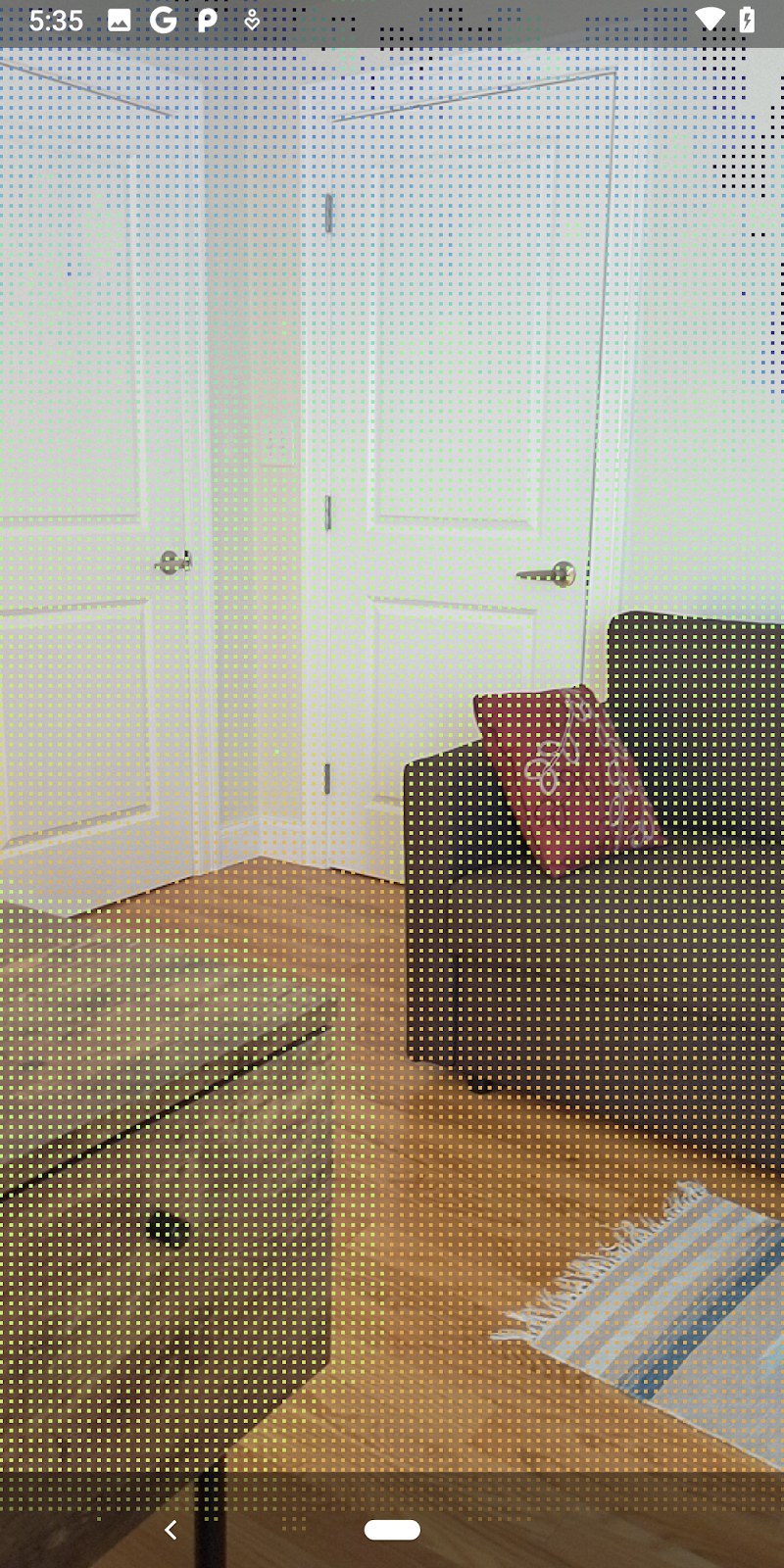
完成这些更改后,应用现在应该可以成功构建并显示深度点云。
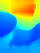
| 原始深度点云图示例
|
7. 分析 3D 点云(第 3 部分)
确认深度数据存在于 AR 会话后,您便可以对其进行分析。用于分析深度的一个重要工具是每个像素的 confidence 值。使用置信度值分析 3D 点云。
使低置信度像素失效
您已检索每个深度像素的置信度值,并将其与 DepthData 中的每个点一起保存,但尚未使用。
confidenceNormalized 的值介于 0 到 1 之间,0 表示置信度低,1 表示最高置信度。修改 DepthData 类中的 convertRawDepthImagesTo3dPointBuffer() 方法,以避免保存因置信度过低而无法使用的像素。
final float confidenceNormalized = ((float) (confidencePixelValue & 0xff)) / 255.0f;

// ******** New code to add ************
if (confidenceNormalized < 0.3) {
   // Ignores "low-confidence" pixels.
   continue;
}
// ******** End of new code to add *********
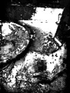
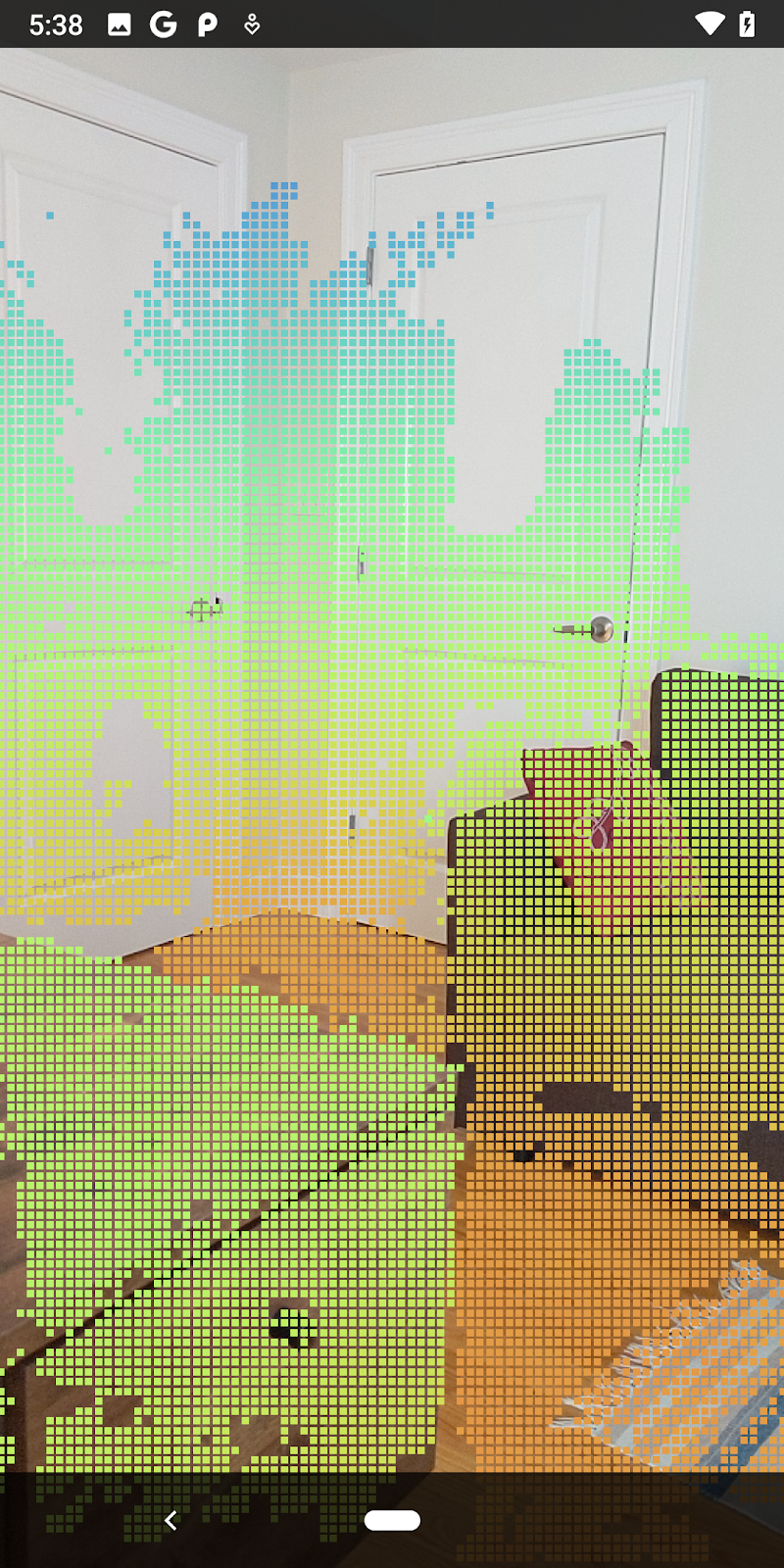
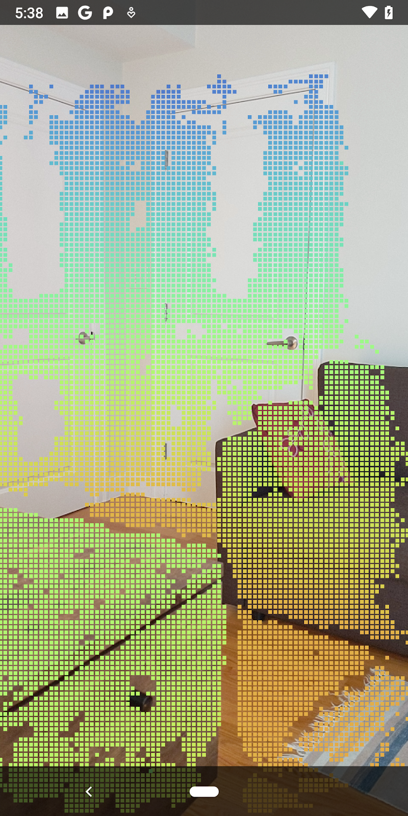
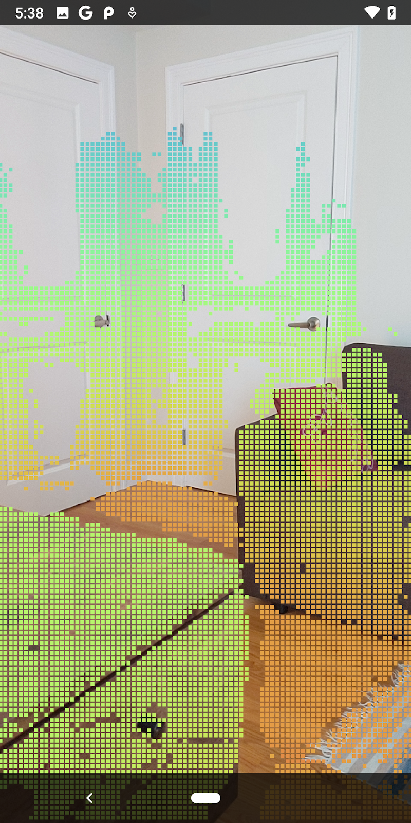
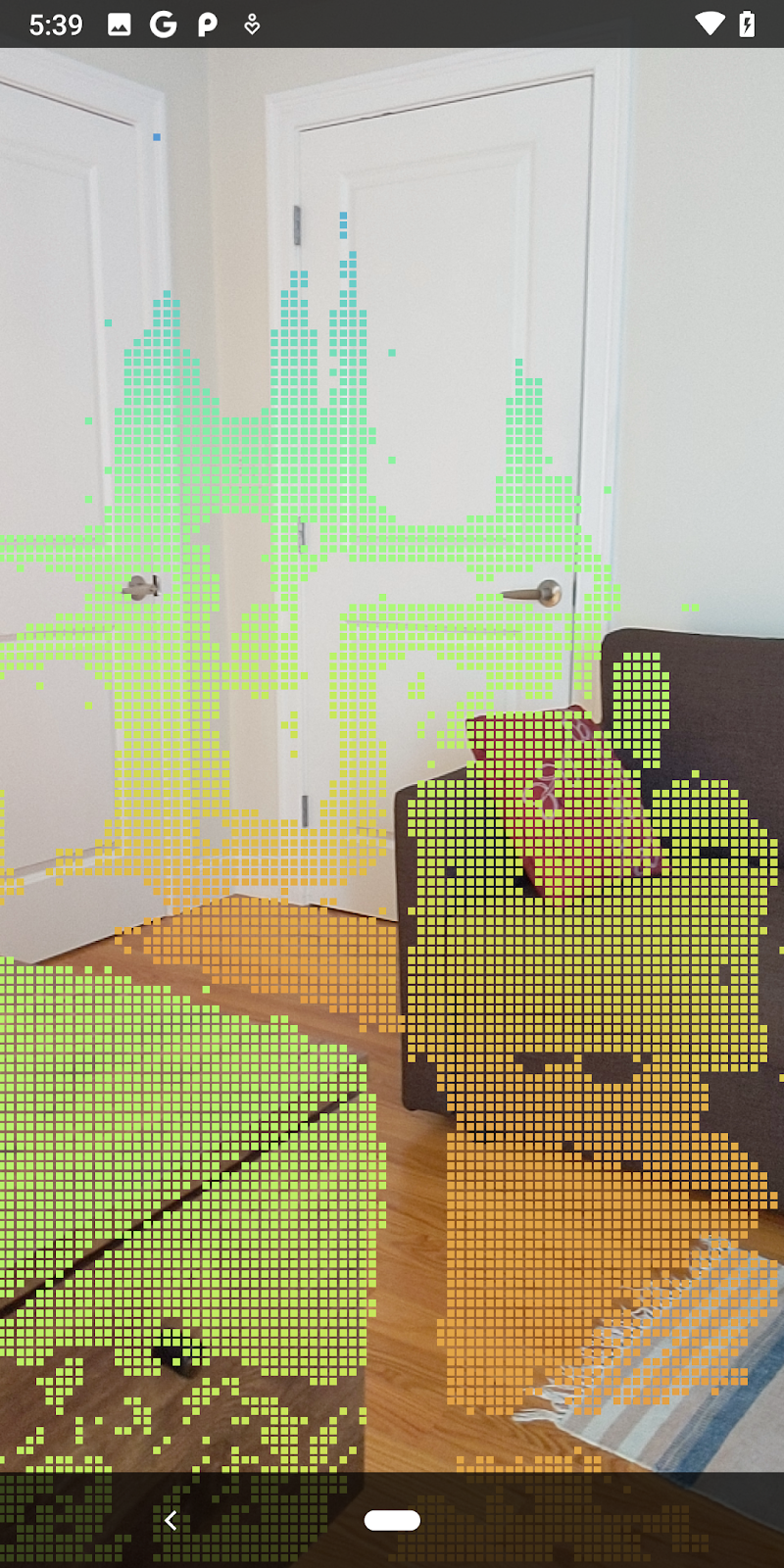
尝试不同的置信度阈值,看看每个级别保留多少个深度点。
|
|
|
|
|
置信度 >= 0.1 | 置信度 >= 0.3 | 置信度 >= 0.5 | 置信度 >= 0.7 | 置信度 >= 0.9 |
按距离过滤像素
您还可以按距离过滤深度像素。接下来的步骤涉及靠近镜头的几何图形。对于性能优化,您可以忽略太远的点。
请使用以下内容更新您刚刚添加的置信度检查代码:
src/main/java/com/google/ar/core/codelab/rawdepth/DepthData.java
if (confidenceNormalized < 0.3 || depthMeters > 1.5) {
    // Ignore "low-confidence" pixels or depth that is too far away.
   continue;
 }
现在,您只会看到置信度高和结束点。
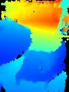
| 距离过滤将 Pointcloud 限制在距离镜头 1.5 米的范围内。 |
比较 3D 点和平面
您可以比较几何图形的 3D 点和平面,并使用它们相互过滤,例如移除靠近观测到的 AR 平面的点。
此步骤将只留下“非平面”元素表示环境中物体表面的点。将 filterUsingPlanes() 方法添加到 DepthData 类的底部。此方法会遍历现有点,对照每个平面检查每个点,并使任何太靠近 AR 平面的点失效,从而留下可突出显示场景中对象的非平面区域。
src/main/java/com/google/ar/core/codelab/rawdepth/DepthData.java
    public static void filterUsingPlanes(FloatBuffer points, Collection<Plane> allPlanes) {
        float[] planeNormal = new float[3];

        // Allocate the output buffer.
        int numPoints = points.remaining() / DepthData.FLOATS_PER_POINT;

        // Check each plane against each point.
        for (Plane plane : allPlanes) {
            if (plane.getTrackingState() != TrackingState.TRACKING || plane.getSubsumedBy() != null) {
                continue;
            }

            // Compute the normal vector of the plane.
            Pose planePose = plane.getCenterPose();
            planePose.getTransformedAxis(1, 1.0f, planeNormal, 0);

            // Filter points that are too close to the plane.
            for (int index = 0; index < numPoints; ++index) {
                // Retrieves the next point.
                final float x = points.get(FLOATS_PER_POINT * index);
                final float y = points.get(FLOATS_PER_POINT * index + 1);
                final float z = points.get(FLOATS_PER_POINT * index + 2);

                // Transform point to be in world coordinates, to match plane info.
                float distance = (x - planePose.tx()) * planeNormal[0]
                        + (y - planePose.ty()) * planeNormal[1]
                        + (z - planePose.tz()) * planeNormal[2];
                // Controls the size of objects detected.
                // Smaller values mean smaller objects will be kept.
                // Larger values will only allow detection of larger objects, but also helps reduce noise.
                if (Math.abs(distance) > 0.03) {
                    continue;  // Keep this point, since it's far enough away from the plane.
                }

                // Invalidate points that are too close to planar surfaces.
                points.put(FLOATS_PER_POINT * index, 0);
                points.put(FLOATS_PER_POINT * index + 1, 0);
                points.put(FLOATS_PER_POINT * index + 2, 0);
                points.put(FLOATS_PER_POINT * index + 3, 0);
            }
        }
    }
您可以将此方法添加到 onDrawFrame 方法中的 RawDepthCodelabActivity:
//  ********** New code to add ************
  // Filter the depth data.
  DepthData.filterUsingPlanes(points, session.getAllTrackables(Plane.class));
//  ********** End new code to add *******

  // Visualize depth points.
  depthRenderer.update(points);
  depthRenderer.draw(camera);
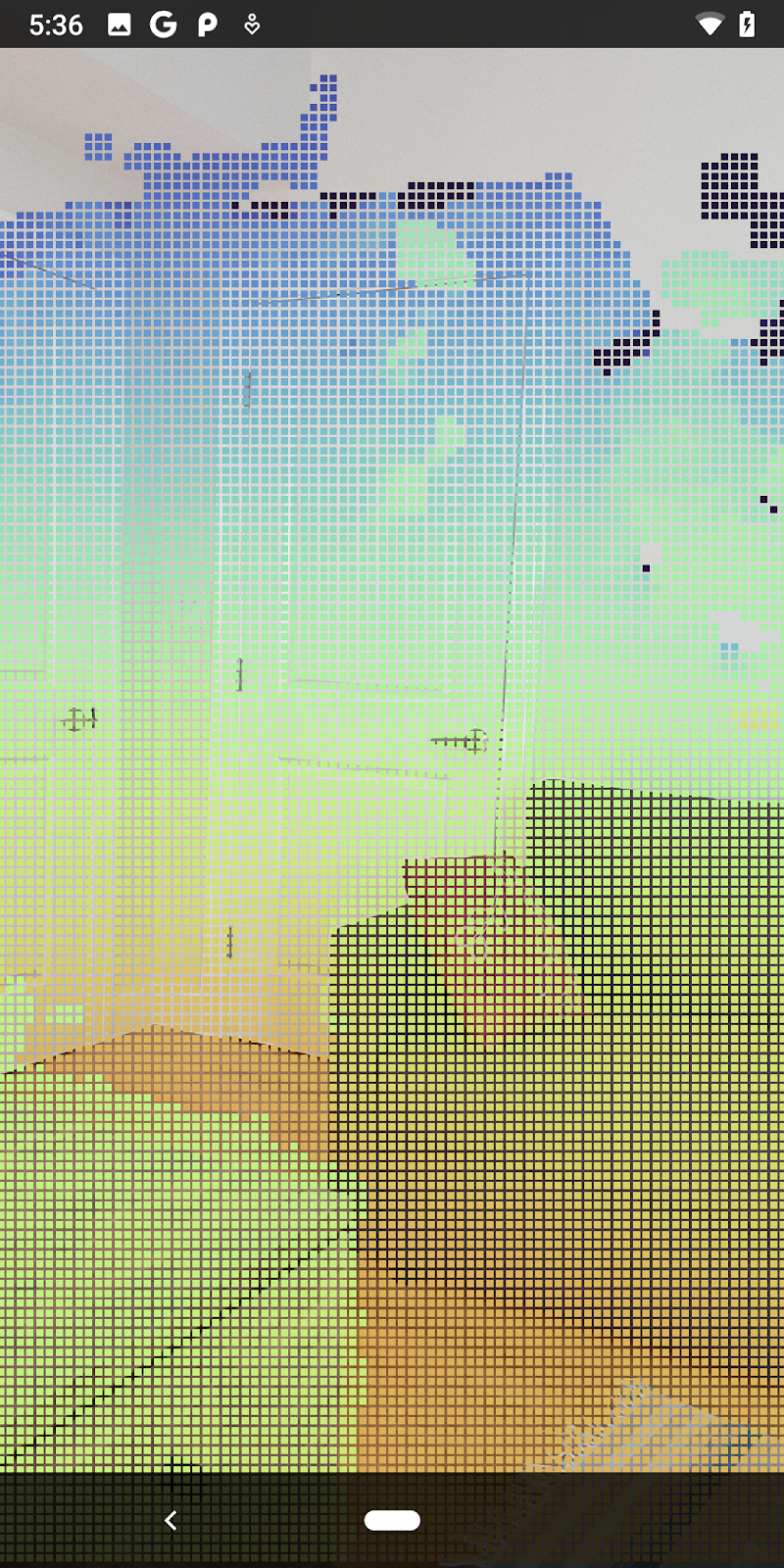
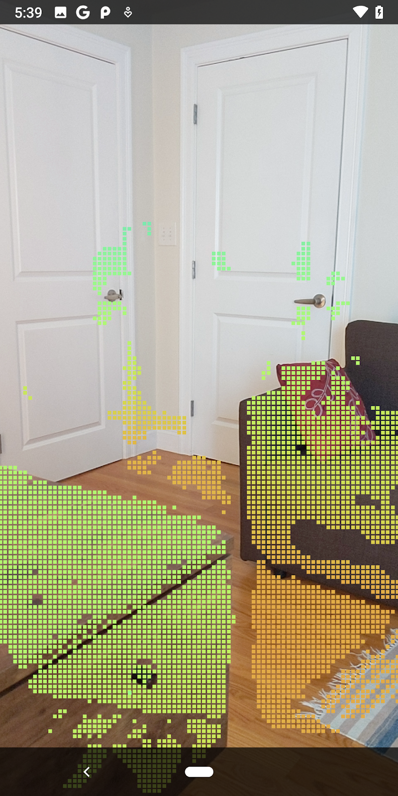
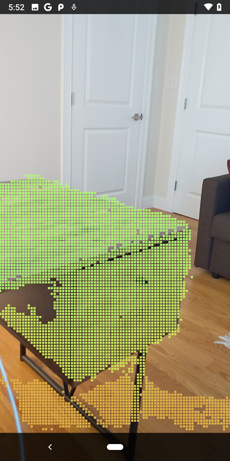
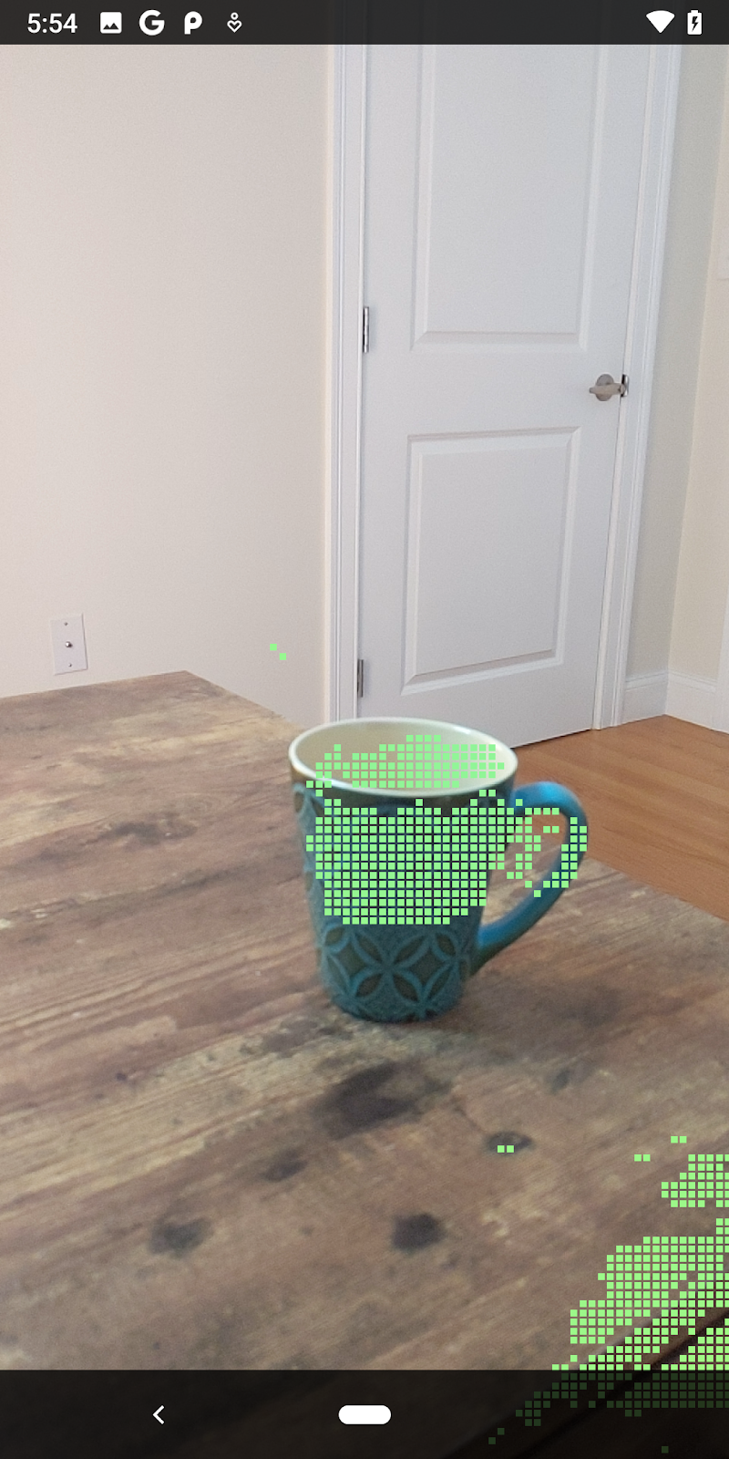
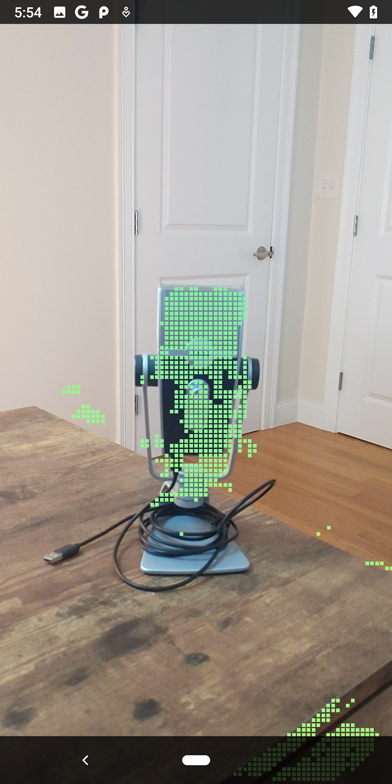
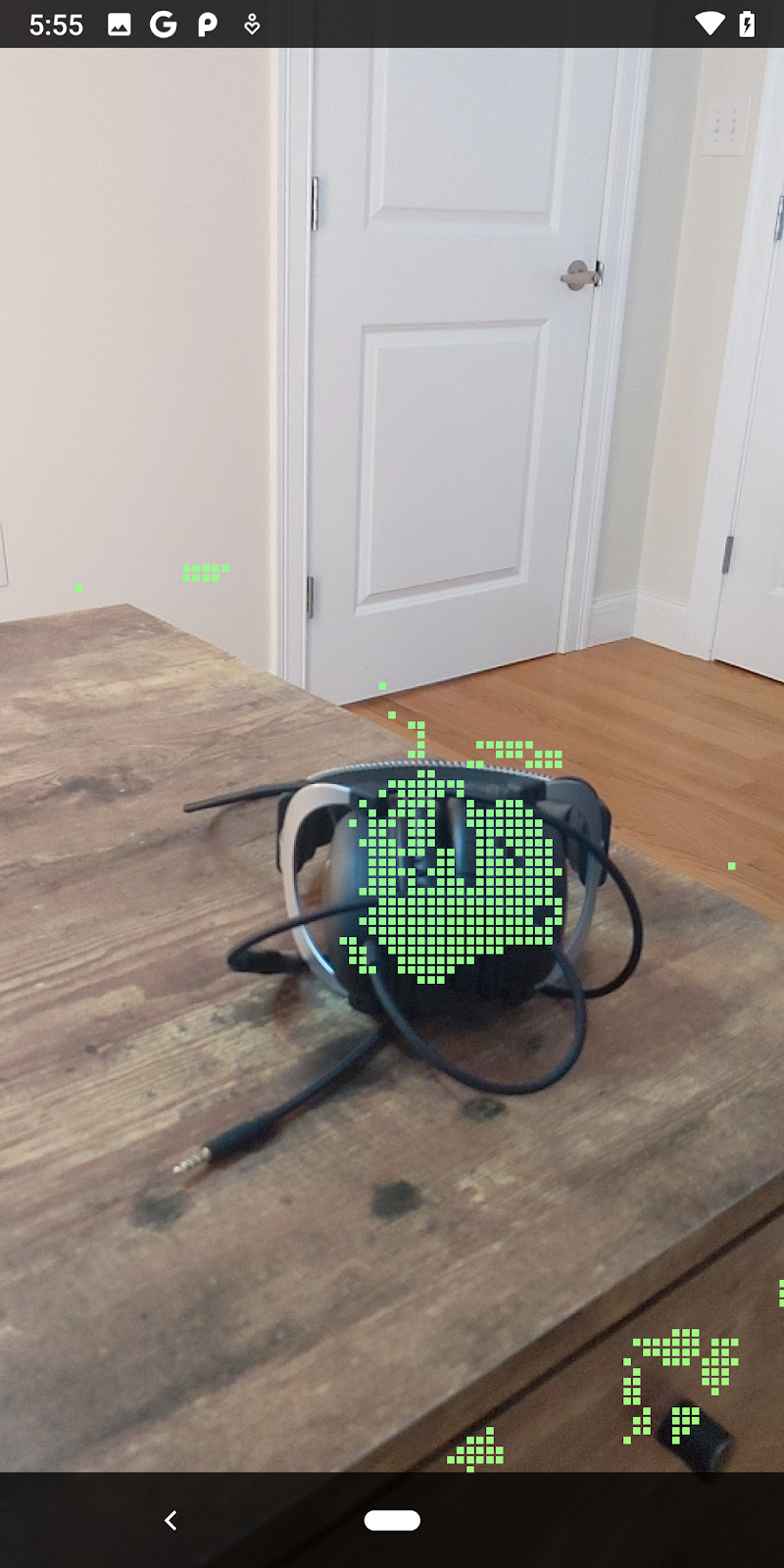
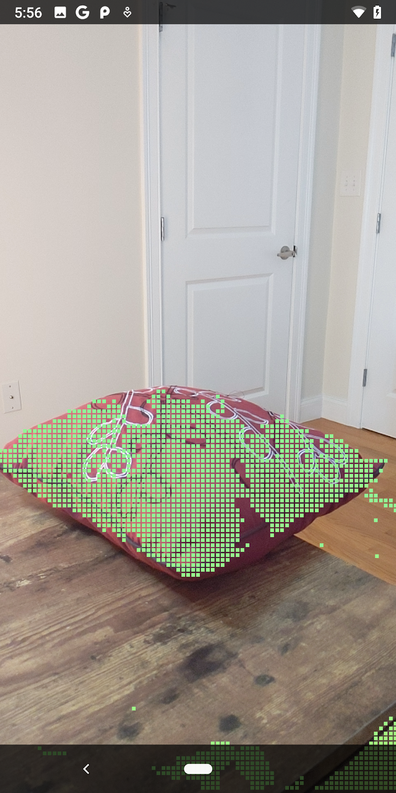
现在,运行此 Codelab 会渲染一部分点。这些点表示场景中的对象,同时会忽略对象所在的平坦表面。您可以使用这些数据将点聚类来估计对象的大小和位置。
|
|
|
|
一杯茶 | 麦克风 | 耳机 | Pillow |
聚类点
此 Codelab 包含一个非常简单的点云聚类算法。更新此 Codelab,将检索到的点云划分到由与轴对齐的边界框定义的聚类。
src/main/java/com/google/ar/core/codelab/rawdepth/RawDepthCodelabActivity.java
import com.google.ar.core.codelab.common.helpers.AABB;
import com.google.ar.core.codelab.common.helpers.PointClusteringHelper;
import com.google.ar.core.codelab.common.rendering.BoxRenderer;
import java.util.List;
将 BoxRenderer 与其他渲染程序一起添加到此类在文件顶部。
private final BoxRenderer boxRenderer = new BoxRenderer();
在 onSurfaceCreated() 方法中,添加以下代码以及其他渲染程序:
boxRenderer.createOnGlThread(/*context=*/this);
最后,将以下几行代码添加到 RawDepthCodelabActivity 内的 onDrawFrame() 中,将检索到的点云分组为聚类,并将结果渲染为与轴对齐的边界框。
      // Visualize depth points.
      depthRenderer.update(points);
      depthRenderer.draw(camera);

// ************ New code to add ***************

      // Draw boxes around clusters of points.
      PointClusteringHelper clusteringHelper = new PointClusteringHelper(points);
      List<AABB> clusters = clusteringHelper.findClusters();
      for (AABB aabb : clusters) {
        boxRenderer.draw(aabb, camera);
      }

// ************ End new code to add ***************
|
|
|
|
一杯茶 | 麦克风 | 耳机 | Pillow |
现在,您可以通过 ARCore 会话检索原始深度,将深度信息转换为 3D 点云,并对这些点执行基本的过滤和渲染操作。
8. 构建、运行、测试
构建、运行和测试您的应用。
构建并运行应用
请按照以下步骤构建和运行您的应用:
- 通过 USB 插入支持 ARCore 的设备。
- 使用菜单栏中的 ► 按钮运行您的项目。
- 等待应用构建并部署到您的设备中。
首次尝试将应用部署到设备时,您需要执行以下操作
允许 USB 调试
。选择“OK”以继续。
首次在设备上运行应用时,系统会询问是否为应用授予使用设备相机的权限。您必须授予该权限才能继续使用 AR 功能。
测试您的应用
运行应用时,您可以手持设备、在空间中移动、缓慢扫描某个区域,以此测试应用的基本行为。先尝试收集至少 10 秒的数据,再从多个方向扫描该区域,然后执行下一步。
9. 恭喜
恭喜!您已成功使用 Google 的 ARCore Raw Depth API 构建并运行了您的第一个基于深度的增强现实应用。我们非常期待看到您将构建的应用!
10. 问题排查
设置 Android 设备用于开发
- 使用一根 USB 线将设备连接到开发机器。如果您要在 Windows 上开发,可能需要为设备安装相应的 USB 驱动程序。
- 执行以下步骤,在开发者选项窗口中启用 USB 调试:
- 打开设置应用。
- 如果您的设备使用 Android v8.0 或更高版本,请选择系统。
- 滚动到底部,然后选择关于手机。
- 滚动到底部,然后点按版本号七次。
- 返回上一屏幕,滚动到底部,然后点按开发者选项。
- 在开发者选项窗口中,向下滚动以找到并启用 USB 调试。
如需详细了解此流程,请访问 Google 的 Android 开发者网站。
与许可相关的构建失败
如果您遇到与许可 (Failed to install the following Android SDK packages as some licences have not been accepted) 相关的构建失败问题,可以使用以下命令来查看并接受这些许可:
cd <path to Android SDK>
tools/bin/sdkmanager --licenses