
1. 事前準備
ARCore 這個平台可讓您在行動裝置上建構擴增實境 (AR) 應用程式,ARCore 運用了不同的 API,可讓使用者的裝置觀察及接收環境資訊,並與這項資訊互動。
在本程式碼研究室中,您將逐步建立一個採用 AR 技術的簡易應用程式,且該應用程式採用 ARCore Depth API。
必要條件
本程式碼研究室是為具備 AR 基本概念的開發人員所撰寫。
建構項目
您會建構一個應用程式,使用每個影格的深度圖片,透過視覺元素呈現場景幾何圖形,並在已放置的虛擬資產中執行遮蔽效果。具體而言,您將按照下列特定步驟操作:
- 檢查手機上的 Depth API 支援
- 擷取每個影格的深度圖片
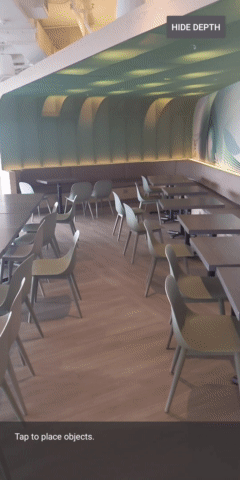
- 以多種方式視覺化呈現深度資訊 (參閱上方動畫)
- 使用深度提高應用程式的寫實程度
- 瞭解如何妥善處理不支援 Depth API 的手機
軟硬體需求
硬體需求
- 支援的 ARCore 裝置,透過 USB 傳輸線連接至開發機器。此裝置也必須支援 Depth API。請參閱這份支援裝置清單。Depth API 僅適用於 Android。
- 為這部裝置啟用 USB 偵錯功能。
軟體需求
- ARCore SDK 1.31.0 以上版本。
- 搭載 Android Studio (3.0 以上版本) 的開發機器。
2. ARCore 和 Depth API
Depth API 使用支援裝置的 RGB 相機製作深度圖 (又稱為深度圖片)。您可以運用深度地圖提供的資訊,讓虛擬物件準確地出現在真實物件前方或後方,進而帶來身歷其境且逼真的使用者體驗。
ARCore Depth API 可讓使用者存取與 ARCore 工作階段提供每個影格相符的深度圖片。每個像素都會提供相機與環境之間的距離測量值,藉此改善 AR 應用程式的真實感。
Depth API 背後的一項重要功能「遮蔽」:讓數位物件精確地相對於真實世界的物件。這會讓物件感覺像是融入使用者的環境。
本程式碼研究室會逐步引導您建構支援 AR 的簡易應用程式,該應用程式會使用深度圖片將虛擬物件遮蔽,以視覺化方式呈現在現實世界中偵測到的幾何形狀。
3. 做好準備
設定開發機器
- 使用 USB 傳輸線將 ARCore 裝置連接至電腦。確認裝置允許 USB 偵錯。
- 開啟終端機並執行
adb devices,如下所示:
adb devices

List of devices attached
<DEVICE_SERIAL_NUMBER>    device
<DEVICE_SERIAL_NUMBER> 是裝置專屬的字串。繼續操作前,請確認每個裝置只有一部裝置。
下載並安裝窗口
- 您可以複製存放區:
git clone https://github.com/googlecodelabs/arcore-depth
或下載 ZIP 檔案並解壓縮:
- 啟動 Android Studio,然後按一下「Open an existing Android Studio project」。
- 找到您在上述步驟中下載 ZIP 檔案的目錄,然後開啟
depth_codelab_io2020目錄。
這是包含多個模組的單一 Gradle 專案。如果 Android Studio 左上方的「Project」窗格未顯示在「Project」窗格中,請按一下下拉式選單中的「Projects」。
結果看起來會像這樣:
| 這項專案包含下列模組:
|
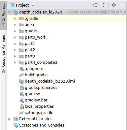
您將在 part0_work 模組中工作。另外,程式碼研究室的每個部分都有完整的解決方案。每個模組都是可建構的應用程式。
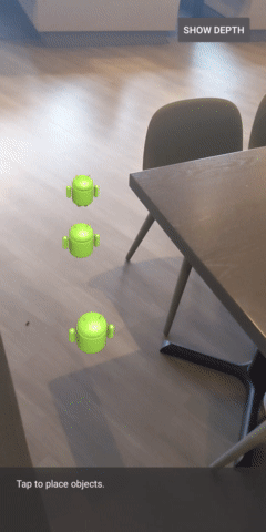
4. 執行入門應用程式
- 按一下「執行」>「執行」執行...>‘part0_work'。在隨即顯示的「Select Deployment Target」對話方塊中,裝置應列於「Connected Devices」下方。
- 選取裝置,然後按一下「OK」。Android Studio 會建構初始應用程式,並在您的裝置上執行。
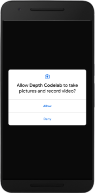
- 應用程式會要求相機權限。輕觸「允許」即可繼續。
| 如何使用應用程式
|
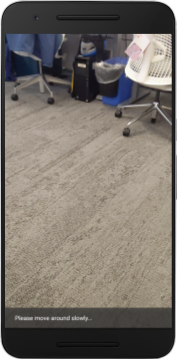
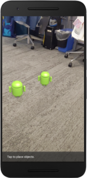
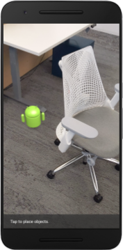
目前,您的應用程式非常簡單,不太瞭解現實世界中的場景幾何形狀。
舉例來說,如果您將 Android 人物放在椅子後方,算繪會懸停在前方,因為應用程式不知道椅子就在那裡,且應該隱藏 Android。
為解決這個問題,我們會使用 Depth API 來改善這個應用程式的沉浸式體驗和寫實程度。
5. 檢查是否支援深度 API (第 1 部分)
ARCore Depth API 只能在部分支援的裝置上執行。使用這些深度圖片將功能整合至應用程式之前,您必須先確認應用程式在支援的裝置上執行。
將新私人成員新增至 DepthCodelabActivity,做為儲存目前裝置是否支援深度的旗標:
private boolean isDepthSupported;
我們可以從建立新的工作階段的 onResume() 函式中填入這個標記。
尋找現有代碼:
// Creates the ARCore session.
session = new Session(/* context= */ this);
將程式碼更新為:
// Creates the ARCore session.
session = new Session(/* context= */ this);
Config config = session.getConfig();
isDepthSupported = session.isDepthModeSupported(Config.DepthMode.AUTOMATIC);
if (isDepthSupported) {
  config.setDepthMode(Config.DepthMode.AUTOMATIC);
} else {
  config.setDepthMode(Config.DepthMode.DISABLED);
}
session.configure(config);
現在 AR 工作階段已正確設定,應用程式知道是否可以使用深度功能。
您也應告知使用者此工作階段是否要採用深度。
在 Snackbar 中新增另一則訊息。將顯示在畫面底部:
// Add this line at the top of the file, with the other messages.
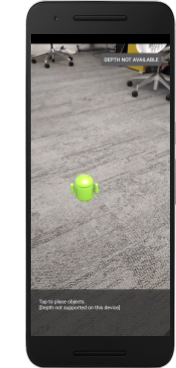
private static final String DEPTH_NOT_AVAILABLE_MESSAGE = "[Depth not supported on this device]";
在 onDrawFrame() 中,您可以視需要分享這則訊息:
// Add this if-statement above messageSnackbarHelper.showMessage(this, messageToShow).
if (!isDepthSupported) {
  messageToShow += "\n" + DEPTH_NOT_AVAILABLE_MESSAGE;
}
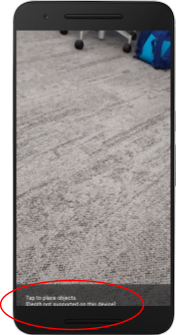
如果應用程式在不支援深度的裝置上執行,您剛剛新增的訊息會顯示在底部:
接下來,您將更新應用程式來呼叫 Depth API,並擷取每個影格的深度圖片。
6. 擷取深度圖片 (第 2 部分)
Depth API 會擷取裝置環境的 3D 觀察結果,並將含有該資料的深度圖片傳回至應用程式。深度影像中的每個像素都代表裝置相機與現實環境之間的距離。
接下來,您就可以運用這些深度圖片改善應用程式的算繪和視覺化效果。第一步是擷取每個影格的深度圖片,然後將該紋理繫結給 GPU 使用。
首先,請在專案中新增類別。DepthTextureHandler 負責擷取指定 ARCore 框架的深度圖片。
新增這個檔案:
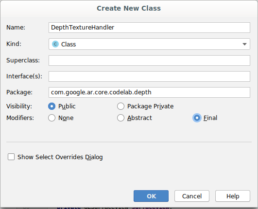
src/main/java/com/google/ar/core/codelab/depth/DepthTextureHandler.java
package com.google.ar.core.codelab.depth;

import static android.opengl.GLES20.GL_CLAMP_TO_EDGE;
import static android.opengl.GLES20.GL_TEXTURE_2D;
import static android.opengl.GLES20.GL_TEXTURE_MAG_FILTER;
import static android.opengl.GLES20.GL_TEXTURE_MIN_FILTER;
import static android.opengl.GLES20.GL_TEXTURE_WRAP_S;
import static android.opengl.GLES20.GL_TEXTURE_WRAP_T;
import static android.opengl.GLES20.GL_UNSIGNED_BYTE;
import static android.opengl.GLES20.glBindTexture;
import static android.opengl.GLES20.glGenTextures;
import static android.opengl.GLES20.glTexImage2D;
import static android.opengl.GLES20.glTexParameteri;
import static android.opengl.GLES30.GL_LINEAR;
import static android.opengl.GLES30.GL_RG;
import static android.opengl.GLES30.GL_RG8;

import android.media.Image;
import com.google.ar.core.Frame;
import com.google.ar.core.exceptions.NotYetAvailableException;

/** Handle RG8 GPU texture containing a DEPTH16 depth image. */
public final class DepthTextureHandler {

  private int depthTextureId = -1;
  private int depthTextureWidth = -1;
  private int depthTextureHeight = -1;

  /**
   * Creates and initializes the depth texture. This method needs to be called on a
   * thread with a EGL context attached.
   */
  public void createOnGlThread() {
    int[] textureId = new int[1];
    glGenTextures(1, textureId, 0);
    depthTextureId = textureId[0];
    glBindTexture(GL_TEXTURE_2D, depthTextureId);
    glTexParameteri(GL_TEXTURE_2D, GL_TEXTURE_WRAP_S, GL_CLAMP_TO_EDGE);
    glTexParameteri(GL_TEXTURE_2D, GL_TEXTURE_WRAP_T, GL_CLAMP_TO_EDGE);
    glTexParameteri(GL_TEXTURE_2D, GL_TEXTURE_MIN_FILTER, GL_LINEAR);
    glTexParameteri(GL_TEXTURE_2D, GL_TEXTURE_MAG_FILTER, GL_LINEAR);
  }

  /**
   * Updates the depth texture with the content from acquireDepthImage16Bits().
   * This method needs to be called on a thread with an EGL context attached.
   */
  public void update(final Frame frame) {
    try {
      Image depthImage = frame.acquireDepthImage16Bits();
      depthTextureWidth = depthImage.getWidth();
      depthTextureHeight = depthImage.getHeight();
      glBindTexture(GL_TEXTURE_2D, depthTextureId);
      glTexImage2D(
          GL_TEXTURE_2D,
          0,
          GL_RG8,
          depthTextureWidth,
          depthTextureHeight,
          0,
          GL_RG,
          GL_UNSIGNED_BYTE,
          depthImage.getPlanes()[0].getBuffer());
      depthImage.close();
    } catch (NotYetAvailableException e) {
      // This normally means that depth data is not available yet.
    }
  }

  public int getDepthTexture() {
    return depthTextureId;
  }

  public int getDepthWidth() {
    return depthTextureWidth;
  }

  public int getDepthHeight() {
    return depthTextureHeight;
  }
}
現在,您要將這個類別的例項新增至 DepthCodelabActivity,確保取得每個影格的深度圖片易於存取。
在 DepthCodelabActivity.java 中,新增新類別的例項做為私人成員變數:
private final DepthTextureHandler depthTexture = new DepthTextureHandler();
接下來,請更新 onSurfaceCreated() 方法以初始化此紋理,以便 GPU 著色器使用:
// Put this at the top of the "try" block in onSurfaceCreated().
depthTexture.createOnGlThread();
最後,您想在每個影格中,使用最新的深度圖片填入這個紋理,方法是在從 session 擷取的最新影格上呼叫您在上述步驟中建立的 update() 方法。
由於此應用程式的深度支援並非強制規定,因此請只在使用深度時才使用這項呼叫。
// Add this just after "frame" is created inside onDrawFrame().
if (isDepthSupported) {
  depthTexture.update(frame);
}
現在您就會產生每個影格都更新的深度圖片。並可供著色器使用。
不過,應用程式的行為還沒有改變。接下來,您將運用深度圖片改善應用程式。
7. 轉譯深度圖片 (第 3 部分)
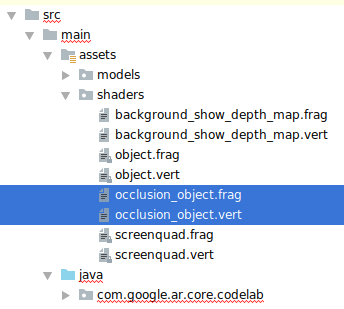
現在您有了深度圖片,接下來會想要看看效果如何。在本節中,您將在應用程式中新增按鈕,呈現每個影格的深度。
新增著色器
您可以透過多種方式觀看深度圖片,下列著色器提供簡易的顏色對應視覺化。
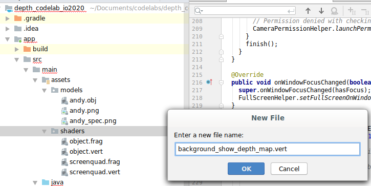
| 新增 .vert 著色器在 Android Studio 中:
|
在新檔案中,加入下列程式碼:
src/main/assets/shaders/background_show_depth_map.vert
attribute vec4 a_Position;
attribute vec2 a_TexCoord;

varying vec2 v_TexCoord;

void main() {
   v_TexCoord = a_TexCoord;
   gl_Position = a_Position;
}
重複上述步驟,讓片段著色器在同一目錄中,並命名為 background_show_depth_map.frag。
在這個新檔案中加入以下程式碼:
src/main/assets/shaders/background_show_depth_map.frag
precision mediump float;
uniform sampler2D u_Depth;
varying vec2 v_TexCoord;
const highp float kMaxDepth = 20000.0; // In millimeters.

float GetDepthMillimeters(vec4 depth_pixel_value) {
  return 255.0 * (depth_pixel_value.r + depth_pixel_value.g * 256.0);
}

// Returns an interpolated color in a 6 degree polynomial interpolation.
vec3 GetPolynomialColor(in float x,
  in vec4 kRedVec4, in vec4 kGreenVec4, in vec4 kBlueVec4,
  in vec2 kRedVec2, in vec2 kGreenVec2, in vec2 kBlueVec2) {
  // Moves the color space a little bit to avoid pure red.
  // Removes this line for more contrast.
  x = clamp(x * 0.9 + 0.03, 0.0, 1.0);
  vec4 v4 = vec4(1.0, x, x * x, x * x * x);
  vec2 v2 = v4.zw * v4.z;
  return vec3(
    dot(v4, kRedVec4) + dot(v2, kRedVec2),
    dot(v4, kGreenVec4) + dot(v2, kGreenVec2),
    dot(v4, kBlueVec4) + dot(v2, kBlueVec2)
  );
}

// Returns a smooth Percept colormap based upon the Turbo colormap.
vec3 PerceptColormap(in float x) {
  const vec4 kRedVec4 = vec4(0.55305649, 3.00913185, -5.46192616, -11.11819092);
  const vec4 kGreenVec4 = vec4(0.16207513, 0.17712472, 15.24091500, -36.50657960);
  const vec4 kBlueVec4 = vec4(-0.05195877, 5.18000081, -30.94853351, 81.96403246);
  const vec2 kRedVec2 = vec2(27.81927491, -14.87899417);
  const vec2 kGreenVec2 = vec2(25.95549545, -5.02738237);
  const vec2 kBlueVec2 = vec2(-86.53476570, 30.23299484);
  const float kInvalidDepthThreshold = 0.01;
  return step(kInvalidDepthThreshold, x) *
         GetPolynomialColor(x, kRedVec4, kGreenVec4, kBlueVec4,
                            kRedVec2, kGreenVec2, kBlueVec2);
}

void main() {
  vec4 packed_depth = texture2D(u_Depth, v_TexCoord.xy);
  highp float depth_mm = GetDepthMillimeters(packed_depth);
  highp float normalized_depth = depth_mm / kMaxDepth;
  vec4 depth_color = vec4(PerceptColormap(normalized_depth), 1.0);
  gl_FragColor = depth_color;
}
接著,請更新 BackgroundRenderer 類別,以使用位於 src/main/java/com/google/ar/core/codelab/common/rendering/BackgroundRenderer.java 中的這些新著色器。
將檔案路徑新增至類別頂端的著色器:
// Add these under the other shader names at the top of the class.
private static final String DEPTH_VERTEX_SHADER_NAME = "shaders/background_show_depth_map.vert";
private static final String DEPTH_FRAGMENT_SHADER_NAME = "shaders/background_show_depth_map.frag";
請新增更多成員變數至 BackgroundRenderer 類別,因為該類別將執行兩個著色器:
// Add to the top of file with the rest of the member variables.
private int depthProgram;
private int depthTextureParam;
private int depthTextureId = -1;
private int depthQuadPositionParam;
private int depthQuadTexCoordParam;
新增填入這些欄位的新方法:
// Add this method below createOnGlThread().
public void createDepthShaders(Context context, int depthTextureId) throws IOException {
  int vertexShader =
      ShaderUtil.loadGLShader(
          TAG, context, GLES20.GL_VERTEX_SHADER, DEPTH_VERTEX_SHADER_NAME);
  int fragmentShader =
      ShaderUtil.loadGLShader(
          TAG, context, GLES20.GL_FRAGMENT_SHADER, DEPTH_FRAGMENT_SHADER_NAME);

  depthProgram = GLES20.glCreateProgram();
  GLES20.glAttachShader(depthProgram, vertexShader);
  GLES20.glAttachShader(depthProgram, fragmentShader);
  GLES20.glLinkProgram(depthProgram);
  GLES20.glUseProgram(depthProgram);
  ShaderUtil.checkGLError(TAG, "Program creation");

  depthTextureParam = GLES20.glGetUniformLocation(depthProgram, "u_Depth");
  ShaderUtil.checkGLError(TAG, "Program parameters");

  depthQuadPositionParam = GLES20.glGetAttribLocation(depthProgram, "a_Position");
  depthQuadTexCoordParam = GLES20.glGetAttribLocation(depthProgram, "a_TexCoord");

  this.depthTextureId = depthTextureId;
}
新增這個方法,以便在每個影格上使用這些著色器進行繪製:
// Put this at the bottom of the file.
public void drawDepth(@NonNull Frame frame) {
  if (frame.hasDisplayGeometryChanged()) {
    frame.transformCoordinates2d(
        Coordinates2d.OPENGL_NORMALIZED_DEVICE_COORDINATES,
        quadCoords,
        Coordinates2d.TEXTURE_NORMALIZED,
        quadTexCoords);
  }

  if (frame.getTimestamp() == 0 || depthTextureId == -1) {
    return;
  }

  // Ensure position is rewound before use.
  quadTexCoords.position(0);

  // No need to test or write depth, the screen quad has arbitrary depth, and is expected
  // to be drawn first.
  GLES20.glDisable(GLES20.GL_DEPTH_TEST);
  GLES20.glDepthMask(false);

  GLES20.glActiveTexture(GLES20.GL_TEXTURE0);
  GLES20.glBindTexture(GLES20.GL_TEXTURE_2D, depthTextureId);
  GLES20.glUseProgram(depthProgram);
  GLES20.glUniform1i(depthTextureParam, 0);

  // Set the vertex positions and texture coordinates.
  GLES20.glVertexAttribPointer(
        depthQuadPositionParam, COORDS_PER_VERTEX, GLES20.GL_FLOAT, false, 0, quadCoords);
  GLES20.glVertexAttribPointer(
        depthQuadTexCoordParam, TEXCOORDS_PER_VERTEX, GLES20.GL_FLOAT, false, 0, quadTexCoords);

  // Draws the quad.
  GLES20.glEnableVertexAttribArray(depthQuadPositionParam);
  GLES20.glEnableVertexAttribArray(depthQuadTexCoordParam);
  GLES20.glDrawArrays(GLES20.GL_TRIANGLE_STRIP, 0, 4);
  GLES20.glDisableVertexAttribArray(depthQuadPositionParam);
  GLES20.glDisableVertexAttribArray(depthQuadTexCoordParam);

  // Restore the depth state for further drawing.
  GLES20.glDepthMask(true);
  GLES20.glEnable(GLES20.GL_DEPTH_TEST);

  ShaderUtil.checkGLError(TAG, "BackgroundRendererDraw");
}
新增切換鈕
現在,您已能夠算繪深度圖,請使用!新增一個按鈕,可開啟或關閉這項功能。
在 DepthCodelabActivity 檔案頂端,為按鈕新增匯入項目:
import android.widget.Button;
更新類別以新增布林值成員,指出深度算繪是否已切換:(預設為關閉):
private boolean showDepthMap = false;
接著,在 onCreate() 方法尾端加入控制 showDepthMap 布林值的按鈕:
final Button toggleDepthButton = (Button) findViewById(R.id.toggle_depth_button);
    toggleDepthButton.setOnClickListener(
        view -> {
          if (isDepthSupported) {
            showDepthMap = !showDepthMap;
            toggleDepthButton.setText(showDepthMap ? R.string.hide_depth : R.string.show_depth);
          } else {
            showDepthMap = false;
            toggleDepthButton.setText(R.string.depth_not_available);
          }
        });
將這些字串新增至 res/values/strings.xml:
<string translatable="false" name="show_depth">Show Depth</string>
<string translatable="false" name="hide_depth">Hide Depth</string>
<string translatable="false" name="depth_not_available">Depth Not Available</string>
請將此按鈕新增至 res/layout/activity_main.xml 中的應用程式版面配置底部:
<Button
    android:id="@+id/toggle_depth_button"
    android:layout_width="wrap_content"
    android:layout_height="wrap_content"
    android:layout_margin="20dp"
    android:gravity="center"
    android:text="@string/show_depth"
    android:layout_alignParentRight="true"
    android:layout_alignParentTop="true"/>
該按鈕現在可控制布林值 showDepthMap 的值。使用這個標記可控制是否要算繪深度地圖。
返回 DepthCodelabActivity 中的 onDrawFrame() 方法,新增:
// Add this snippet just under backgroundRenderer.draw(frame);
if (showDepthMap) {
  backgroundRenderer.drawDepth(frame);
}
在 onSurfaceCreated() 中新增下列程式碼,將深度紋理傳遞至 backgroundRenderer:
// Add to onSurfaceCreated() after backgroundRenderer.createonGlThread(/*context=*/ this);
backgroundRenderer.createDepthShaders(/*context=*/ this, depthTexture.getDepthTexture());
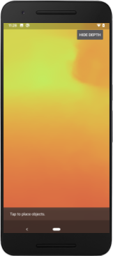
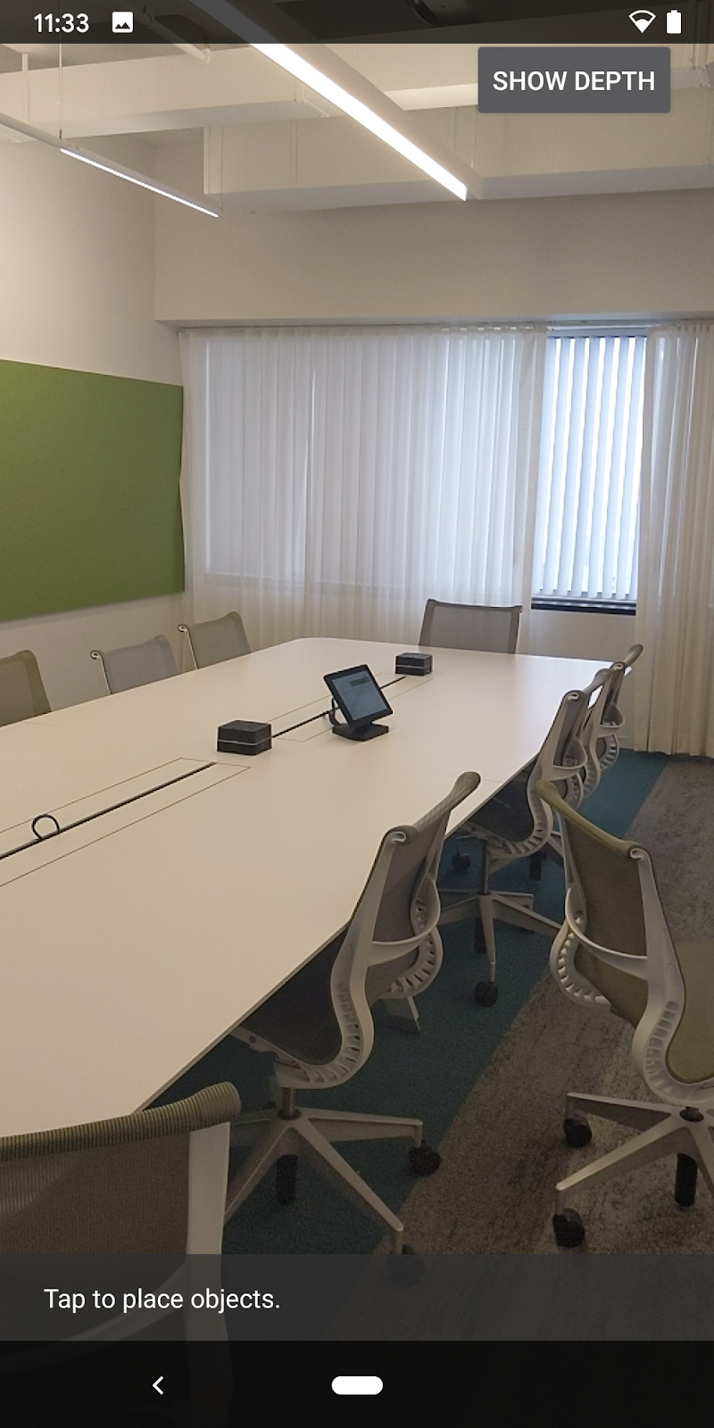
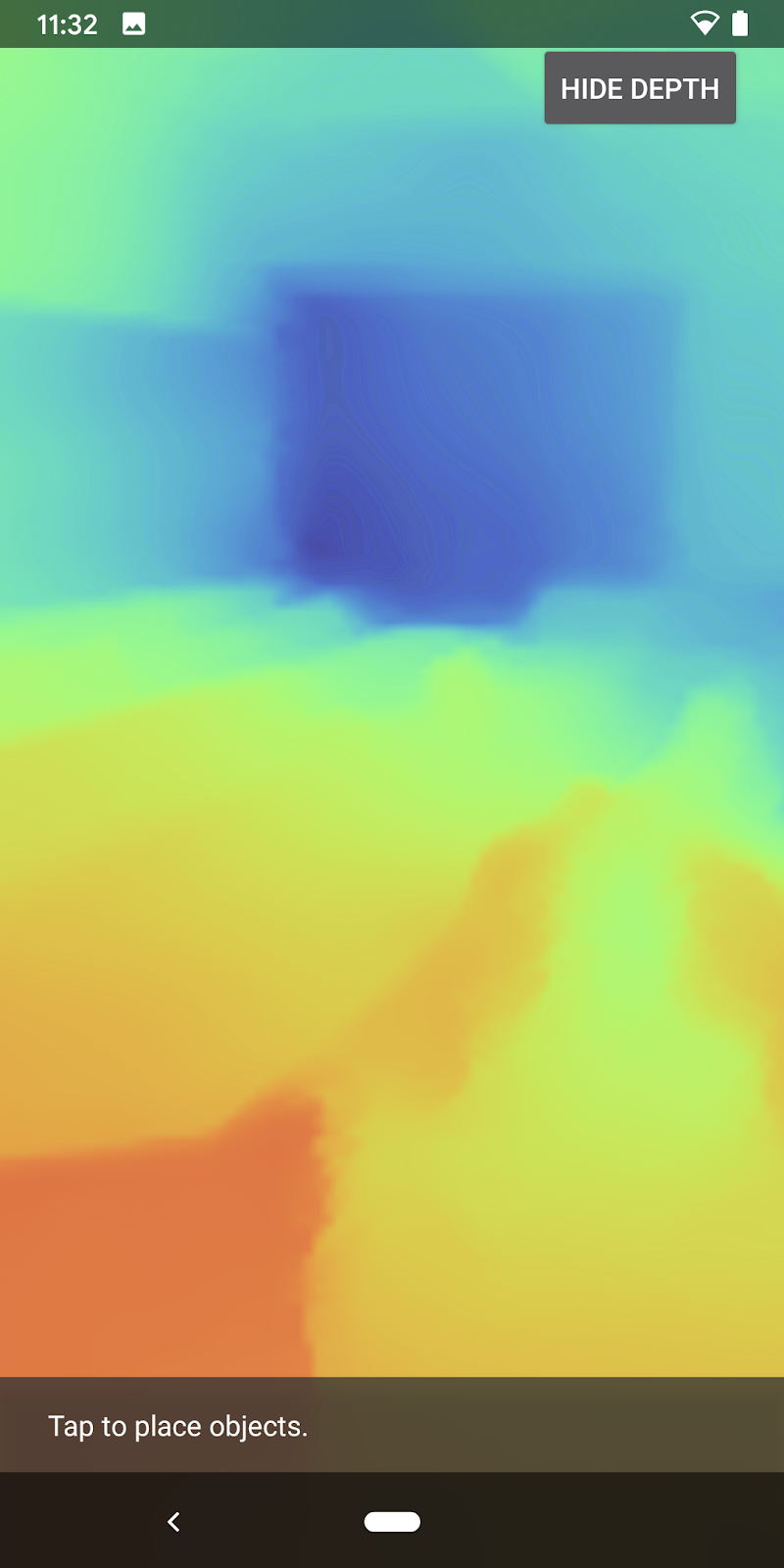
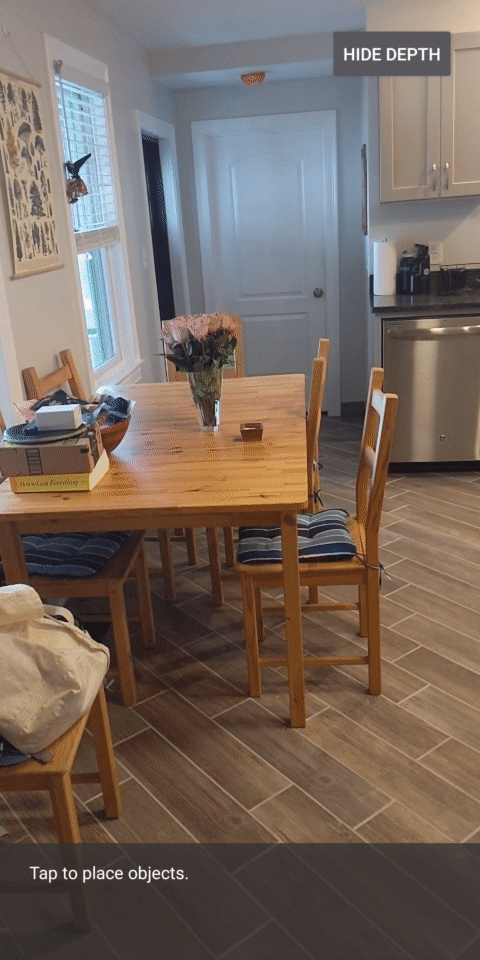
現在,按下畫面右上角的按鈕,即可查看每個畫面的深度圖片。
|
| ||
在不支援 Depth API 的情況下執行 | 以深度 API 支援執行 | ||
[選用] 花俏深度動畫
應用程式目前會直接顯示深度圖。紅色像素代表鄰近的區域。藍色像素表示距離較遠的區域。
|
|
傳達深度資訊的方法有很多種,在本節中,您將修改著色器,定期閃爍著色器,只顯示會重複移開相機的錶帶深度。
請先將這些變數新增至 background_show_depth_map.frag 的頂端:
uniform float u_DepthRangeToRenderMm;
const float kDepthWidthToRenderMm = 350.0;
- 然後在著色器的
main()函式中使用這些值,篩選要納入哪些像素的深度值:
// Add this line at the end of main().
gl_FragColor.a = clamp(1.0 - abs((depth_mm - u_DepthRangeToRenderMm) / kDepthWidthToRenderMm), 0.0, 1.0);
接下來,請更新 BackgroundRenderer.java 以保留這些著色器參數。將下列欄位新增至類別頂端:
private static final float MAX_DEPTH_RANGE_TO_RENDER_MM = 20000.0f;
private float depthRangeToRenderMm = 0.0f;
private int depthRangeToRenderMmParam;
在 createDepthShaders() 方法中,新增下列內容,以便比對這些參數與著色器程式:
depthRangeToRenderMmParam = GLES20.glGetUniformLocation(depthProgram, "u_DepthRangeToRenderMm");
- 最後,您可以在
drawDepth()方法中長期控制這個範圍。新增下列程式碼,在每次繪製影格時遞增這個範圍:
// Enables alpha blending.
GLES20.glEnable(GLES20.GL_BLEND);
GLES20.glBlendFunc(GLES20.GL_SRC_ALPHA, GLES20.GL_ONE_MINUS_SRC_ALPHA);

// Updates range each time draw() is called.
depthRangeToRenderMm += 50.0f;
if (depthRangeToRenderMm > MAX_DEPTH_RANGE_TO_RENDER_MM) {
  depthRangeToRenderMm = 0.0f;
}

// Passes latest value to the shader.
GLES20.glUniform1f(depthRangeToRenderMmParam, depthRangeToRenderMm);
現在畫面深度看起來會像動畫脈衝,從場景中流動。
你可以變更這裡提供的值,讓脈衝速度變慢、更快、更寬、更窄等等。你也可以試著以全新方式改變著色器,以顯示深度資訊!
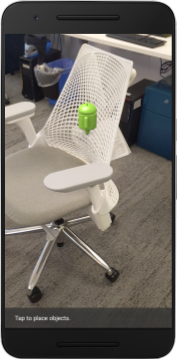
8. 使用深度 API 進行遮蔽 (第 4 部分)
現在您將在應用程式中處理物件遮蔽。
「遮蔽」是指虛擬物件無法完整轉譯時會發生的情況,因為虛擬物件和相機之間會有真實物體。管理 AR 體驗的關鍵在於妥善管理遮蔽物,
即時正確算繪虛擬物件,可提升擴增場景的真實性和可信度。如需更多範例,請觀看我們的影片,瞭解如何使用 Depth API 混合實境。
在本節中,您將更新應用程式,改為只在提供深度時加入虛擬物件。
新增物件著色器
與先前的章節相同,您將新增著色器來支援深度資訊。這次您可以複製現有的物件著色器,並新增遮蔽功能。
請務必保留兩個版本的物件著色器,以便您的應用程式能夠在執行階段決定是否支援深度。
複製 src/main/assets/shaders 目錄中的 object.vert 和 object.frag 著色器檔案。
|
|
在 occlusion_object.vert 中,在 main() 上方新增下列變數:
varying vec3 v_ScreenSpacePosition;
在 main() 的底部設定這個變數:
v_ScreenSpacePosition = gl_Position.xyz / gl_Position.w;
在檔案頂端在 main() 上方新增下列變數,即可更新 occlusion_object.frag:
varying vec3 v_ScreenSpacePosition;

uniform sampler2D u_Depth;
uniform mat3 u_UvTransform;
uniform float u_DepthTolerancePerMm;
uniform float u_OcclusionAlpha;
uniform float u_DepthAspectRatio;
- 您可以在著色器的
main()上方新增下列輔助函式,方便處理深度資訊:
float GetDepthMillimeters(in vec2 depth_uv) {
  // Depth is packed into the red and green components of its texture.
  // The texture is a normalized format, storing millimeters.
  vec3 packedDepthAndVisibility = texture2D(u_Depth, depth_uv).xyz;
  return dot(packedDepthAndVisibility.xy, vec2(255.0, 256.0 * 255.0));
}

// Returns linear interpolation position of value between min and max bounds.
// E.g., InverseLerp(1100, 1000, 2000) returns 0.1.
float InverseLerp(in float value, in float min_bound, in float max_bound) {
  return clamp((value - min_bound) / (max_bound - min_bound), 0.0, 1.0);
}

// Returns a value between 0.0 (not visible) and 1.0 (completely visible)
// Which represents how visible or occluded is the pixel in relation to the
// depth map.
float GetVisibility(in vec2 depth_uv, in float asset_depth_mm) {
  float depth_mm = GetDepthMillimeters(depth_uv);

  // Instead of a hard z-buffer test, allow the asset to fade into the
  // background along a 2 * u_DepthTolerancePerMm * asset_depth_mm
  // range centered on the background depth.
  float visibility_occlusion = clamp(0.5 * (depth_mm - asset_depth_mm) /
    (u_DepthTolerancePerMm * asset_depth_mm) + 0.5, 0.0, 1.0);

  // Depth close to zero is most likely invalid, do not use it for occlusions.
  float visibility_depth_near = 1.0 - InverseLerp(
      depth_mm, /*min_depth_mm=*/150.0, /*max_depth_mm=*/200.0);

  // Same for very high depth values.
  float visibility_depth_far = InverseLerp(
      depth_mm, /*min_depth_mm=*/17500.0, /*max_depth_mm=*/20000.0);

  float visibility =
    max(max(visibility_occlusion, u_OcclusionAlpha),
      max(visibility_depth_near, visibility_depth_far));

  return visibility;
}
現在更新 occlusion_object.frag 中的 main(),以提供深度感知功能並套用遮蔽效果。在檔案底部加入下列程式碼:
const float kMToMm = 1000.0;
float asset_depth_mm = v_ViewPosition.z * kMToMm * -1.;
vec2 depth_uvs = (u_UvTransform * vec3(v_ScreenSpacePosition.xy, 1)).xy;
gl_FragColor.a *= GetVisibility(depth_uvs, asset_depth_mm);
現在您已擁有新版物件著色器,接下來可以修改轉譯器程式碼。
轉譯物件遮蔽
接著建立 ObjectRenderer 類別的副本,可在 src/main/java/com/google/ar/core/codelab/common/rendering/ObjectRenderer.java 中找到。
- 選取
ObjectRenderer類別 - 按一下滑鼠右鍵 >複製
- 選取 rendering 資料夾
- 按一下滑鼠右鍵 >貼上
- 將類別重新命名為
OcclusionObjectRenderer
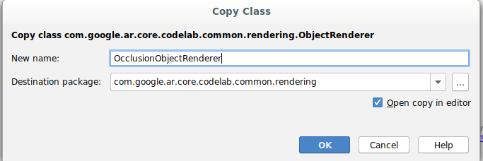
經過重新命名的新類別現在應該會顯示在相同的資料夾中:
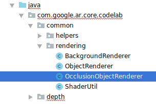
開啟新建立的 OcclusionObjectRenderer.java,然後變更檔案頂端的著色器路徑:
private static final String VERTEX_SHADER_NAME = "shaders/occlusion_object.vert";
private static final String FRAGMENT_SHADER_NAME = "shaders/occlusion_object.frag";
- 將這些深度相關成員變數與類別頂端的其他變數一起新增。這些變數會調整遮蔽邊框的銳利度。
// Shader location: depth texture
private int depthTextureUniform;

// Shader location: transform to depth uvs
private int depthUvTransformUniform;

// Shader location: depth tolerance property
private int depthToleranceUniform;

// Shader location: maximum transparency for the occluded part.
private int occlusionAlphaUniform;

private int depthAspectRatioUniform;

private float[] uvTransform = null;
private int depthTextureId;
使用類別頂端的預設值建立以下成員變數:
// These values will be changed each frame based on the distance to the object.
private float depthAspectRatio = 0.0f;
private final float depthTolerancePerMm = 0.015f;
private final float occlusionsAlpha = 0.0f;
初始化 createOnGlThread() 方法中著色器的統一參數:
// Occlusions Uniforms.  Add these lines before the first call to ShaderUtil.checkGLError
// inside the createOnGlThread() method.
depthTextureUniform = GLES20.glGetUniformLocation(program, "u_Depth");
depthUvTransformUniform = GLES20.glGetUniformLocation(program, "u_UvTransform");
depthToleranceUniform = GLES20.glGetUniformLocation(program, "u_DepthTolerancePerMm");
occlusionAlphaUniform = GLES20.glGetUniformLocation(program, "u_OcclusionAlpha");
depthAspectRatioUniform = GLES20.glGetUniformLocation(program, "u_DepthAspectRatio");
- 請更新
draw()方法,確保這些值在每次產生時更新:
// Add after other GLES20.glUniform calls inside draw().
GLES20.glActiveTexture(GLES20.GL_TEXTURE1);
GLES20.glBindTexture(GLES20.GL_TEXTURE_2D, depthTextureId);
GLES20.glUniform1i(depthTextureUniform, 1);
GLES20.glUniformMatrix3fv(depthUvTransformUniform, 1, false, uvTransform, 0);
GLES20.glUniform1f(depthToleranceUniform, depthTolerancePerMm);
GLES20.glUniform1f(occlusionAlphaUniform, occlusionsAlpha);
GLES20.glUniform1f(depthAspectRatioUniform, depthAspectRatio);
在 draw() 中新增以下幾行,即可在算繪時啟用混合模式,以便在虛擬物件遮住時套用透明度:
// Add these lines just below the code-block labeled "Enable vertex arrays"
GLES20.glEnable(GLES20.GL_BLEND);
GLES20.glBlendFunc(GLES20.GL_SRC_ALPHA, GLES20.GL_ONE_MINUS_SRC_ALPHA);
// Add these lines just above the code-block labeled "Disable vertex arrays"
GLES20.glDisable(GLES20.GL_BLEND);
GLES20.glDepthMask(true);
- 新增下列方法,以便
OcclusionObjectRenderer的呼叫端提供深度資訊:
// Add these methods at the bottom of the OcclusionObjectRenderer class.
public void setUvTransformMatrix(float[] transform) {
  uvTransform = transform;
}

public void setDepthTexture(int textureId, int width, int height) {
  depthTextureId = textureId;
  depthAspectRatio = (float) width / (float) height;
}
控管物件遮蔽
現在,您已建立新的 OcclusionObjectRenderer,可以將其新增至 DepthCodelabActivity,並選擇使用遮蔽轉譯作業的時間和方式。
將 OcclusionObjectRenderer 的執行個體新增至活動,以啟用此邏輯,讓 ObjectRenderer 和 OcclusionObjectRenderer 都是 DepthCodelabActivity 的成員:
// Add this include at the top of the file.
import com.google.ar.core.codelab.common.rendering.OcclusionObjectRenderer;
// Add this member just below the existing "virtualObject", so both are present.
private final OcclusionObjectRenderer occludedVirtualObject = new OcclusionObjectRenderer();
- 接下來,您可以根據目前裝置是否支援 Depth API,控制使用這個
occludedVirtualObject的時機。在onSurfaceCreated方法中的virtualObject設定下方,新增以下幾行內容:
if (isDepthSupported) {
  occludedVirtualObject.createOnGlThread(/*context=*/ this, "models/andy.obj", "models/andy.png");
  occludedVirtualObject.setDepthTexture(
     depthTexture.getDepthTexture(),
     depthTexture.getDepthWidth(),
     depthTexture.getDepthHeight());
  occludedVirtualObject.setMaterialProperties(0.0f, 2.0f, 0.5f, 6.0f);
}
在不支援深度的裝置中,系統會建立 occludedVirtualObject 執行個體,但未使用的執行個體。在深度較常的手機上,兩個版本都會初始化,而系統在繪圖時會使用哪個版本的轉譯器。
在 onDrawFrame() 方法中,找出現有程式碼:
virtualObject.updateModelMatrix(anchorMatrix, scaleFactor);
virtualObject.draw(viewmtx, projmtx, colorCorrectionRgba, OBJECT_COLOR);
將這段程式碼取代為下列程式碼:
if (isDepthSupported) {
  occludedVirtualObject.updateModelMatrix(anchorMatrix, scaleFactor);
  occludedVirtualObject.draw(viewmtx, projmtx, colorCorrectionRgba, OBJECT_COLOR);
} else {
  virtualObject.updateModelMatrix(anchorMatrix, scaleFactor);
  virtualObject.draw(viewmtx, projmtx, colorCorrectionRgba, OBJECT_COLOR);
}
最後,確認深度圖片已正確對應到輸出內容。由於深度圖片的解析度不同,顯示比例可能與螢幕不同,因此本身和相機圖片之間的紋理座標可能不同。
- 將
getTextureTransformMatrix()輔助方法新增至檔案底部。這個方法會傳回轉換矩陣,套用後能讓螢幕空間 UV 與用於算繪相機動態饋給的四重紋理座標正確配對。而且會將裝置螢幕方向納入考量。
private static float[] getTextureTransformMatrix(Frame frame) {
  float[] frameTransform = new float[6];
  float[] uvTransform = new float[9];
  // XY pairs of coordinates in NDC space that constitute the origin and points along the two
  // principal axes.
  float[] ndcBasis = {0, 0, 1, 0, 0, 1};

  // Temporarily store the transformed points into outputTransform.
  frame.transformCoordinates2d(
      Coordinates2d.OPENGL_NORMALIZED_DEVICE_COORDINATES,
      ndcBasis,
      Coordinates2d.TEXTURE_NORMALIZED,
      frameTransform);

  // Convert the transformed points into an affine transform and transpose it.
  float ndcOriginX = frameTransform[0];
  float ndcOriginY = frameTransform[1];
  uvTransform[0] = frameTransform[2] - ndcOriginX;
  uvTransform[1] = frameTransform[3] - ndcOriginY;
  uvTransform[2] = 0;
  uvTransform[3] = frameTransform[4] - ndcOriginX;
  uvTransform[4] = frameTransform[5] - ndcOriginY;
  uvTransform[5] = 0;
  uvTransform[6] = ndcOriginX;
  uvTransform[7] = ndcOriginY;
  uvTransform[8] = 1;

  return uvTransform;
}
getTextureTransformMatrix() 要求檔案頂端須有下列匯入項目:
import com.google.ar.core.Coordinates2d;
您想要在每次螢幕紋理變更時 (例如螢幕旋轉) 時,計算這些紋理座標之間的轉換。這項功能受到管制,
在檔案頂端新增下列旗標:
// Add this member at the top of the file.
private boolean calculateUVTransform = true;
- 在
onDrawFrame()中,檢查在影格和相機建立後,是否需要重新運算儲存的轉換:
// Add these lines inside onDrawFrame() after frame.getCamera().
if (frame.hasDisplayGeometryChanged() || calculateUVTransform) {
  calculateUVTransform = false;
  float[] transform = getTextureTransformMatrix(frame);
  occludedVirtualObject.setUvTransformMatrix(transform);
}
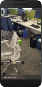
完成這些變更後,您現在可以在虛擬物件遮蔽下執行應用程式!
您的應用程式現在應該能在所有手機上正常執行,並在系統支援時自動使用深度排除。
|
| ||
執行支援 Depth API 的應用程式 | 在不支援 Depth API 的情況下執行應用程式 | ||
9. [選用] 提升遮蔽品質
上述實作的深度遮蔽方法,可呈現銳利邊界的遮蔽方式。隨著攝影機移動到較遠處,深度測量結果的精確度就會降低,因而導致視覺失真。
為緩解這個問題,我們可以在遮蔽測試中加入額外的模糊處理,為隱藏的虛擬物件創造更流暢的邊緣。
occlusion_object.frag
在 occlusion_object.frag 頂端新增下列統一變數:
uniform float u_OcclusionBlurAmount;
將這個輔助函式新增至著色器中 main() 的正上方,以將核心模糊效果套用至遮蔽取樣:
float GetBlurredVisibilityAroundUV(in vec2 uv, in float asset_depth_mm) {
  // Kernel used:
  // 0   4   7   4   0
  // 4   16  26  16  4
  // 7   26  41  26  7
  // 4   16  26  16  4
  // 0   4   7   4   0
  const float kKernelTotalWeights = 269.0;
  float sum = 0.0;

  vec2 blurriness = vec2(u_OcclusionBlurAmount,
                         u_OcclusionBlurAmount * u_DepthAspectRatio);

  float current = 0.0;

  current += GetVisibility(uv + vec2(-1.0, -2.0) * blurriness, asset_depth_mm);
  current += GetVisibility(uv + vec2(+1.0, -2.0) * blurriness, asset_depth_mm);
  current += GetVisibility(uv + vec2(-1.0, +2.0) * blurriness, asset_depth_mm);
  current += GetVisibility(uv + vec2(+1.0, +2.0) * blurriness, asset_depth_mm);
  current += GetVisibility(uv + vec2(-2.0, +1.0) * blurriness, asset_depth_mm);
  current += GetVisibility(uv + vec2(+2.0, +1.0) * blurriness, asset_depth_mm);
  current += GetVisibility(uv + vec2(-2.0, -1.0) * blurriness, asset_depth_mm);
  current += GetVisibility(uv + vec2(+2.0, -1.0) * blurriness, asset_depth_mm);
  sum += current * 4.0;

  current = 0.0;
  current += GetVisibility(uv + vec2(-2.0, -0.0) * blurriness, asset_depth_mm);
  current += GetVisibility(uv + vec2(+2.0, +0.0) * blurriness, asset_depth_mm);
  current += GetVisibility(uv + vec2(+0.0, +2.0) * blurriness, asset_depth_mm);
  current += GetVisibility(uv + vec2(-0.0, -2.0) * blurriness, asset_depth_mm);
  sum += current * 7.0;

  current = 0.0;
  current += GetVisibility(uv + vec2(-1.0, -1.0) * blurriness, asset_depth_mm);
  current += GetVisibility(uv + vec2(+1.0, -1.0) * blurriness, asset_depth_mm);
  current += GetVisibility(uv + vec2(-1.0, +1.0) * blurriness, asset_depth_mm);
  current += GetVisibility(uv + vec2(+1.0, +1.0) * blurriness, asset_depth_mm);
  sum += current * 16.0;

  current = 0.0;
  current += GetVisibility(uv + vec2(+0.0, +1.0) * blurriness, asset_depth_mm);
  current += GetVisibility(uv + vec2(-0.0, -1.0) * blurriness, asset_depth_mm);
  current += GetVisibility(uv + vec2(-1.0, -0.0) * blurriness, asset_depth_mm);
  current += GetVisibility(uv + vec2(+1.0, +0.0) * blurriness, asset_depth_mm);
  sum += current * 26.0;

  sum += GetVisibility(uv , asset_depth_mm) * 41.0;

  return sum / kKernelTotalWeights;
}
取代 main() 中的以下現有一行:
gl_FragColor.a *= GetVisibility(depth_uvs, asset_depth_mm);
取代為:
gl_FragColor.a *= GetBlurredVisibilityAroundUV(depth_uvs, asset_depth_mm);
如要充分利用這項新的著色器功能,請更新轉譯器。
OcclusionObjectRenderer.java
在類別頂端新增下列成員變數:
private int occlusionBlurUniform;
private final float occlusionsBlur = 0.01f;
在 createOnGlThread 方法中新增以下內容:
// Add alongside the other calls to GLES20.glGetUniformLocation.
occlusionBlurUniform = GLES20.glGetUniformLocation(program, "u_OcclusionBlurAmount");
在 draw 方法中新增以下內容:
// Add alongside the other calls to GLES20.glUniform1f.
GLES20.glUniform1f(occlusionBlurUniform, occlusionsBlur);
| 視覺比較現在這些變更使遮蔽邊界更順暢。 |
10. Build-Run-Test
建構並執行應用程式
- 透過 USB 插入 Android 裝置。
- 選擇 [檔案] > 建構及執行。
- 另存新檔:ARCodeLab.apk。
- 等待應用程式建構並部署至您的裝置。
首次嘗試在裝置上部署應用程式時:
- 您必須在裝置上允許 USB 偵錯。選取「確定」即可繼續操作。
- 系統會詢問應用程式是否有權使用裝置相機。請授予相關權限,以便繼續使用 AR 功能。
測試應用程式
執行應用程式時,你可以按住裝置、在空間中四處移動,然後慢慢掃描區域,藉此測試應用程式的基本行為。請試著收集至少 10 秒的資料,並從多方向掃描該區域,再前往下一個步驟。
疑難排解
設定開發用的 Android 裝置
- 使用 USB 傳輸線將裝置連接至您開發的機器上。如果您是使用 Windows 進行開發,可能需要為裝置安裝合適的 USB 驅動程式。
- 在「開發人員選項」視窗中按照下列步驟啟用「USB 偵錯」:
- 開啟「設定」應用程式。
- 如果您的裝置使用 Android 8.0 以上版本,請選取「系統」。否則,請繼續下一步。
- 捲動至底部,然後選取「關於手機」。
- 捲動至畫面底部,然後輕觸「版本號碼」7 次。
- 返回上一個畫面,捲動至底部,然後輕觸「開發人員選項」。
- 在「開發人員選項」視窗中,向下捲動並啟用「USB 偵錯」。
如要進一步瞭解這項程序,請前往 Google 的 Android 開發人員網站。
與授權相關的建構錯誤
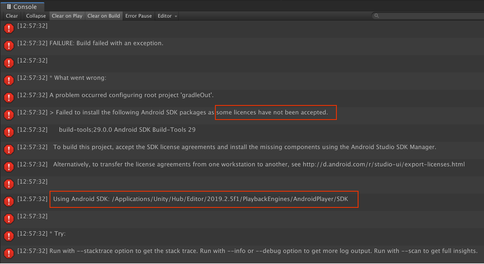
如果您遇到與授權相關的建構失敗問題 (「無法安裝下列 Android SDK 套件,因為尚未接受部分授權」),您可以使用下列指令來查看並接受這些授權:
cd <path to Android SDK>
tools/bin/sdkmanager --licenses
11. 恭喜
恭喜,你使用 Google 的 ARCore Depth API 成功建構並執行第一個深度式擴增實境應用程式!